Introduction
About this document
Thank you for purchasing Cerevo LiveShell W.
This document is a manual explaining how to use the LiveShell W (hereinafter referred to as “this product”). Please read this manual to the end before use, and use this product with a full understanding of how to handle it properly.
Scope of coverage
This manual describes the general information required to use this product, including installation, setup, operating procedures, and restrictions. In addition to this manual, the following documents are provided.
A quick setup guide included with this product
-
We recommend referring to this setup guide when performing the initial setup of this product.
Release notes for each firmware version
Revision Information
This manual is version 3.0.3 (released on 20th May 2026). This manual applies to the following revisions of LiveShell W.
Hardware Revision A.
Revision History
Version 1.0 (Released 18th August 2022)
First Edition
Version 1.1 (Released 30th September 2022)
With the release of firmware version v1.1.0, added explanations related to the newly implemented functions.
Unified the terminology, replacing “system resolution”, which was used in some places, with “system video format”.
Unified the terminology, replacing “Input A” and “Input B” (in Japanese), which were used in some places, with “Input A” and “Input B”.
Other minor corrections, such as typographical errors, were made.
Version 1.2 (Released 12th October 2022)
With the release of firmware version v1.2.0, added explanations related to the newly implemented functions.
Version 1.2.1 (Released 15th October 2022)
With the release of firmware version v1.2.1, updated the revision history.
Made minor corrections to documentation errors in the manual.
Version 1.2.1-b (Released 20th October 2022)
Separated the firmware update guide as a separate document.
Version 1.3.0 (Released 30th November 2022)
With the release of firmware version v1.3.0, revised the descriptions.
With the addition of the function, changed the name “left-right split” to “split screen”.
Version 1.4.0 (Released 27th December 2022)
With the release of firmware version v1.4.0, revised the descriptions.
Version 1.4.1 (Released 28th February 2023)
With the release of firmware version v1.4.1, updated the revision history.
Version 1.5.0 (Released 28th April 2023)
With the release of firmware version v1.5.0, updated the revision history.
Updated the descriptions in the manual with the addition of the new telop (on-screen text) function.
Version 1.6.0 (Released 23rd June 2023)
With the release of firmware version v1.6.0, updated the revision history.
With the addition of the memory function, added descriptions to the manual.
With the addition of the key assignment setting function, added descriptions to the manual.
With the release of the LiveShell ControlPad (product model number CDP-LSC06A), added explanations on how to use the ControlPad.
Version 1.6.1 (Released 26th June 2023)
With the release of firmware version v1.6.1, updated the revision history.
Version 1.6.2 (Released 18th August 2023)
With the release of firmware version v1.6.2, updated the revision history.
Version 2.0.0 (Released 29th May 2024)
With the release of firmware version v2.0.0, updated the revision history.
With the addition of the LiveShell Remote function, added descriptions to the manual.
Added descriptions to the manual about the settings for RTMP/RTMP authentication.
Version 2.0.1 (Released 5th September 2024)
With the release of firmware version v2.0.1, updated the revision history.
Version 2.0.2 (Released 18th March 2025)
With the release of firmware version v2.0.2, updated the revision history.
Version 2.0.3 (Released 2nd July 2025)
With the release of firmware version v2.0.3, updated the revision history.
With the addition of the preamp gain adjustment function for the analog microphone, added descriptions to the manual.
Version 2.1.0 (Released 3rd December 2025)
With the release of the setup guide, added it to the scope of coverage.
Version 3.0.0 (Released 23rd March 2026)
With the release of firmware version v3.0.0, added explanations related to the newly implemented functions.
Changed and added external view diagrams of the main unit.
Changed and added operation images.
Added operating procedures.
Added Useful settings.
Added Error Messages.
Other minor corrections, such as typographical errors, were made.
Version 3.0.3 (Released 20th May 2026)
With the release of firmware version v3.0.3, updated the revision history.
With the addition of the BGM player function, added BGM player and updated the system configuration example and signal flow diagram.
Prerequisite knowledge
This manual assumes that the reader has the following knowledge:
How to interconnect video devices using an HDMI cable
How to interconnect audio equipment using audio signal cables
Basic understanding of local networks using Ethernet (IEEE 802.3) and wireless LAN (IEEE 802.11)
Basic understanding of IP network operation and interface configuration
How to register with a live streaming platform and obtain stream keys, etc.
For your safety
Meaning of symbols
In this chapter, sentences starting with WARNING and CAUTION describe information that is very important for the safe use of this product.WARNING and CAUTION respectively refer to the following.
WARNING
Failure to comply this warning may result in death or serious bodily harm.
CAUTION
Failure to comply this caution may result in bodily injury or equipment damage.
Safety warnings and precautions
In the event of an abnormal situation
WARNING
If abnormal conditions such as smoke or unusual smells come out of this product or cables, etc., stop using it immediately and disconnect the power supply cable.Continued use under such conditions may result in malfunction, electric shock, or fire. After confirming that no smoke is emitted, contact your dealer or our support center. Do not attempt to repair this product by yourself as it is dangerous.
About power supply
WARNING
Use power and power-supply cables that meet all the requirements described in this manual. Using incompatible cables may result in malfunction of this product, electric shock, overheating, smoking, or fire.
WARNING
Never use the power-supply cable if it is damaged, conductor wires are exposed, or is broken. Doing so may result in a malfunction of this product, electric shock, overheating, smoking, or fire.
WARNING
Do not use this product with dust or other foreign matter or liquid adhering to the power-supply connector.Doing so may result in a malfunction of this product, electric shock, overheating, smoking, or fire.
Temperature rise
CAUTION
The surface of this product may become hot due to heat dissipation and may cause burns if touched. Please handle this product with care during and after use until the temperature cools down.
Prohibited acts
WARNING
Do not disassemble or modify this product. Doing so may result in malfunction of this product, electric shock, overheating, smoking, or fire.
WARNING
Do not short-circuit the connectors of this product or connect devices other than those indicated in this manual. Doing so may result in malfunction of this product, electric shock, overheating, smoking, or fire.
WARNING
When connecting external devices to this product, turn off the power of all devices first. Connecting external devices with the power on may cause malfunction or damage to this product.
Installation environment
CAUTION
Do not use this product under the following conditions or environment. Doing so may result in malfunction, failure, or deformation.
Places directly exposed to wind from heaters, air conditioners, etc., or where there is a sudden change in temperature
Places exposed to direct sunlight or in a car under a hot sun
Places subjected to sea breezes or continuous high humidity
In a liquid or in a corrosive atmosphere
Places subject to strong vibrations
Places where there are strong electromagnetic field
Places where static electricity is generated
Other similar conditions
Function overview
This product is a network video encoder equipped with a 2-input video switcher and audio mixer. It has two HDMI video and audio input connectors and can receive video and audio signals from these inputs simultaneously. The video signals are processed through switching, scaling, compositing, and other operations, and then encoded using H.264. The audio signals are mixed with the analog audio input from the LINE and MIC connectors, and then encoded using AAC-LC.
The encoded video and audio streams can be sent to an IP network in real time using protocols such as RTMP and RTSP. The video and audio streams can also be stored on an SD memory card, USB memory device, or similar media.
Names and functions of each part
The names and functions of each part of this product are shown in the figure below.
Front
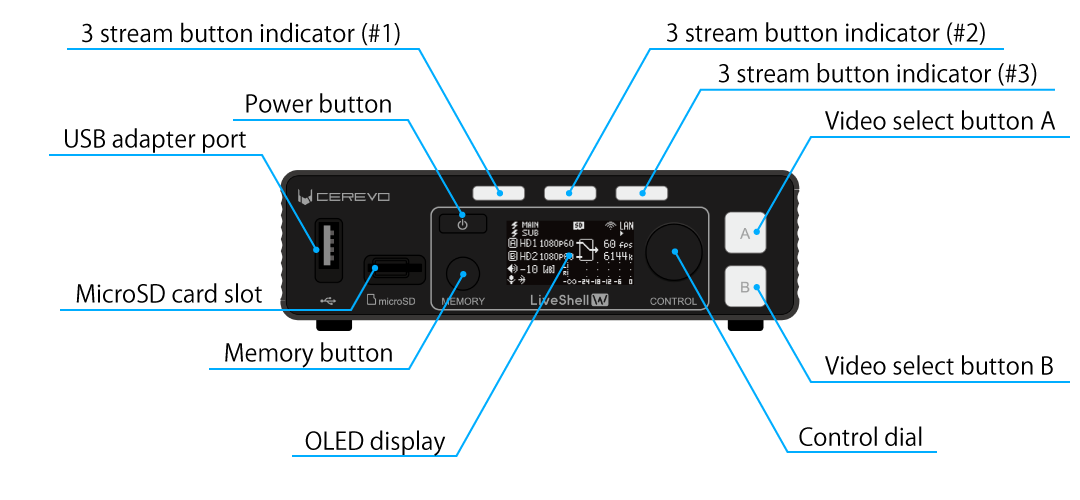
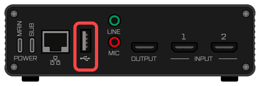
USB adapter port
USB A port for connecting accessories for this product.
MicroSD card slot
This is used to insert a microSD card for video recording.
OLED display
A display for showing the operating status of this product as text and other indicators. A menu is displayed when making settings using the control dial on the main unit.
Power button
A button for turning this product on or off.
→How to start up this product | How to shut down this product
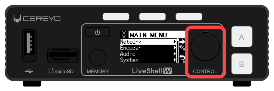
Control dial
This dial is used during the settings and perform other operations on this product.
Memory button
A button for switching the display to memory mode when using the memory function.
Video select buttons
Buttons for selecting the video received from the two HDMI inputs. The buttons are internally illuminated and indicate the selection status by light.
3 stream button indicator
These buttons are used to start and stop live streaming. The button is internally illuminated and indicates the live streaming status by light.
Tip
The descriptions of the button functions apply to the factory default state. The functions assigned to the buttons can be customized using the key assignment settings. →Key Assignment
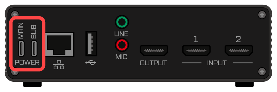
Rear
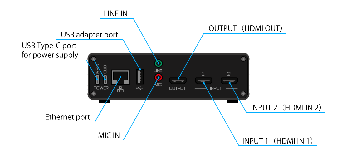
USB Type-C port for power supply
The power input connectors for this product. There are two inputs, MAIN and SUB.
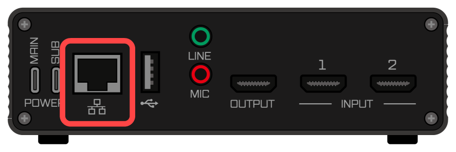
Ethernet port
A 1000BASE-T Gigabit Ethernet interface for connecting this product to a network.
USB adapter port
A USB A connector for connecting a wireless LAN adapter or USB communication adapter to this product.
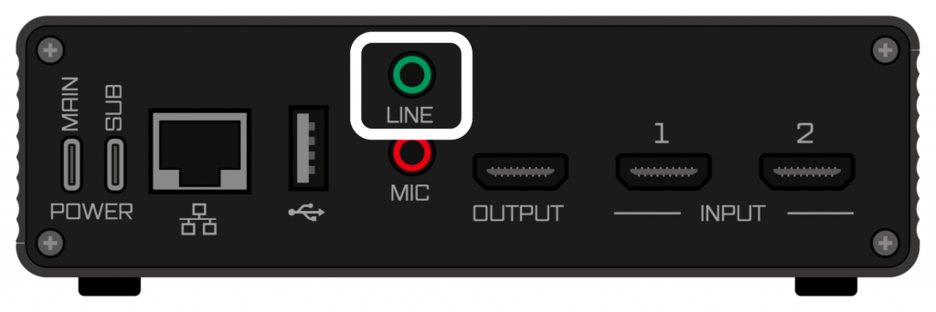
LINE IN
A 3.5 mm stereo jack for inputting line-level analog audio signals to this product.
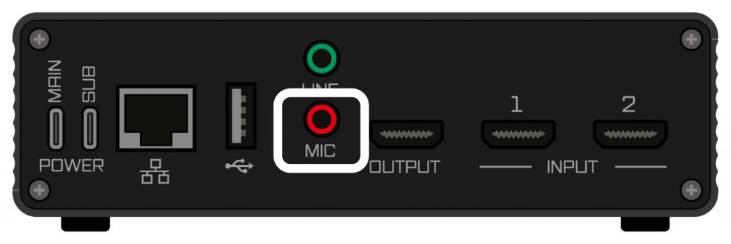
MIC IN
A 3.5 mm monaural jack for inputting microphone-level analog audio signals to this product.
HDMI IN 1
One of the HDMI inputs for inputting video and audio signals to this product.
HDMI IN 2
One of the HDMI inputs for inputting video and audio signals to this product.
HDMI OUT
An HDMI output connector for monitoring the video and audio being streamed by this product.
Side Left
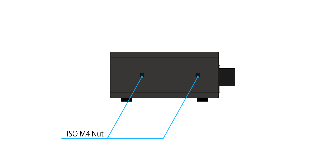
ISO M4 Nut
These nuts are used to secure this product.
Side Right
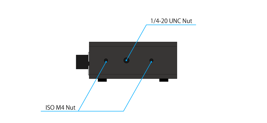
1/4-20 UNC nut
These nuts are to mount this product on a tripod, etc.
ISO M4 Nut
These nuts are used to secure this product.
Bottom
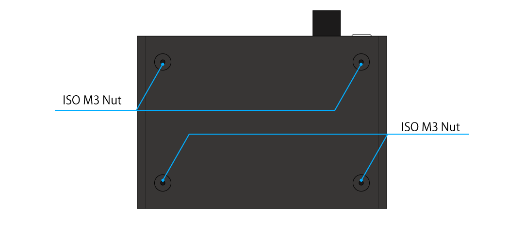
ISO M3 Nut
These nuts are used to secure this product to shelves, etc.
Items you need to prepare in addition to this product
To use this product, you need to separately prepare external devices such as the following (this list is only an example; the devices you actually need vary depending on how you use the product).
A device that can run a web browser for operating this product (PC, tablet, smartphone, etc.)
A video source device capable of outputting video and audio via HDMI, such as a camera
Devices necessary to build a communication network that meets Network requirements
Cables, connectors, and other items for connecting these devices
How to set up and operate the product
There are two ways to change the settings of this product and operate its various functions: using the buttons on the front of the product, or using LiveShell Studio, a web application built into this product. The characteristics of each method are as follows, and you can use them selectively according to the operation you want to perform.
Operation using the buttons on the front of the product
Operation using the buttons on the front of the product has the following characteristics.
It can be used even when this product is not connected to a network (such as before initial setup).
There is no need to prepare an external device, such as a PC for operation.
Some functions cannot be set or operated using this method.
Therefore, it is suitable for simple settings and operations.
Operation using LiveShell Studio
Operation using LiveShell Studio has the following characteristics.
To use LiveShell Studio, the network settings of this product must be completed.
A device that can run a web browser, such as a PC for operation, is required separately.
LiveShell Studio can operate all the functions of this product.
Therefore, it is suitable for more advanced settings and operations.
Operation using LiveShell Remote
LiveShell Remote is a cloud service for remotely operating this product’s LiveShell Studio over the internet. With LiveShell Remote, you can operate this product even when the location where the product is installed and the location of the operating PC are far apart.
To use LiveShell Remote, a separate cloud service usage agreement is required.
In addition, to operate the product with LiveShell Remote, the unit must be registered with the cloud system in advance.
Example of system configuration
The figure below shows a typical configuration example of a streaming system using this product.
                                         LiveShell W
                                    +-------------------+
                                    |                   |
    Power [AC/DC]--- USB Type-C ----| POWER MAIN        |
                                    |                   |
                                    | POWER SUB         |
                                    |                   |
    CAMERA 1   |>[CAM]---- HDMI ----| INPUT 1           |
                                    |                   |
    CAMERA 2   |>[CAM]---- HDMI ----| INPUT 2           |
                                    |                   |
    DISPLAY      [LCD]---- HDMI ----| OUTPUT            |
                                    |                   |
    Music Player [MP]--- 3.5 mm ----| LINE              |
                                    |                   |
    Microphone   [MIC]-- 3.5 mm ----| MIC               |
                                    |                   |
                        +-- UTP ----| ETHERNET          |
                        |           |                   |
                        |           +-------------------+
                        |
                        |           +-------------------+
                        +-----------|                   |
                                    |                   |
    +-----------+                   |                   |
    | Laptop PC |-------------------|    GbE Switch     |
    +-----------+                   |                   |
                    +--------+      |                   |
  The Internet <----| Router |------|                   |
                    +--------+      +-------------------+
Explanation of the system configuration example
In this system configuration example, this product is powered by a single power supply from an AC adapter.
As video sources, two cameras are connected to the HDMI INPUT connectors of this product. This makes it possible to switch and stream the video captured by each camera, or to stream a video that composites the content captured by both cameras, such as picture-in-picture (PinP). In addition, a display is connected to the HDMI OUTPUT connector so that the actual content being streamed can be monitored.
As additional audio sources, analog audio signals from a music player and a microphone are connected to the LINE and MIC connectors of this product, respectively. This allows the microphone to capture the talk of the streamer while also adding the BGM played by the music player to the streamed audio. For BGM playback, instead of an external music player, you can also use the BGM player function built into this product (→BGM player). These audio sources, including the two HDMI audio inputs, can be mixed at any desired level.
For the network connection, an Ethernet (wired LAN) connection is used, and the Ethernet port of this product is connected to a separately prepared Gigabit Ethernet switch. Connectivity from this product to the internet is ensured through a router that serves as the default gateway. In addition, a laptop computer running a web browser is also connected to the same network in order to operate LiveShell Studio.
System configuration variations
In addition to the typical configuration example described in the previous section, the following configurations are also possible.
Use a dual power supply to make the power redundant
Use a PC as a video source instead of a camera
Use only a single video input and stream without using the switcher or compositing functions
Use the product without connecting a display for monitoring
Use the product without inputting analog audio
Connect to the network using a wireless LAN instead of Ethernet
For specific connection and setup methods, please refer to the following chapters.
Signal flow
The signal flow inside this product is shown in the figure below.
                    +-----------------------------------------------------------------------+
                    |                                                                       |
                    |   Video Processor      +---------------+                              |
                    |   ~~~~~~~~~~~~~~~      |               |                              |
                    |                        | Frame sync    |                              |
    [ INPUT 1 ]    >|=== HDMI --> Video A >--| Deinterlacer  |                              |
                    |     |                  | Scaler        |     +------------+           |
                    |     +--> (Audio 1)     |               |     |            |           |
                    |                        | Selector      |>----| H.264 ENC  |-----+     |
                    |                        | Mix/Wipe/PinP |     |            |     |     |
    [ INPUT 2 ]    >|=== HDMI --> Video B >--| Chromakey     |     +------------+     |     |
                    |     |                  |               |                        |     |
                    |     +--> (Audio 2)     | Overlay       |                        |     |
                    |                        |               |                        |     |
                    |                        +---------------+                        |     |
                    |                                |                                |     |
                    |                                |                                |     |
    [ OUTPUT ]     <|=== HDMI ---< Video monitor <---+                                |     |
                    |     |                                                           |     |
                    |     +------< Audio monitor <---+---> (USB Audio Playback)       |     |
                    |                                |                                |     |
                    |                                |                                |     |
                    |   Audio Processor              |                                |     |
                    |   ~~~~~~~~~~~~~~~              |                                |     |
                    |                                |                                |     |
                    |   --> (Audio 1)                |                                |     |
                    |           |            +---------------+                        |     |
                    |   +---------------+    |               |                        |     |
                    |   |   Resampler   |>---|               |                        |     |
                    |   +---------------+    |               |                        |     |
                    |                        |               |                        |     |
                    |                        |               |                        |     |
                    |   --> (Audio 2)        |               |                        |     |
                    |           |            |               |     +-------------+    |     |
                    |   +---------------+    |    Digital    |     |             |    |     |
                    |   |   Resampler   |>---|    mixer      |>----| AAC-LC ENC  |    |     |
                    |   +---------------+    |               |     |             |    |     |
                    |                        |               |     +-------------+    |     |
                    |                        |               |            |           |     |
                    |   --> (USB Audio)      |               |            |           |     |
                    |           |            |               |            |           |     |
                    |   +---------------+    |               |            |           |     |
                    |   |   Resampler   |>---|               |            |           |     |
                    |   +---------------+    |               |            |           |     |
                    |                        |               |            |           |     |
                    |   --> (BGM)            |               |            |           |     |
                    |           |            |               |            |           |     |
                    |   +---------------+    |               |            |           |     |
                    |   |   BGM Player  |>---|               |            |           |     |
                    |   +---------------+    |               |            |           |     |
                    |                        +---------------+            |           |     |
                    |                                |                    |           |     |
                    |   +-----+                      |                    |           |     |
    [ LINE ]       >|---|     |   +-----+    +---------------+            |           |     |
                    |   | MIX |>--| PGA |>---|  16 bit ADC   |            |           |     |
    [ MIC ]        >|---|     |   +-----+    +---------------+            |           |     |
                    |   +-----+                                           |           |     |
                    |                                                     |           |     |
                    |                                                     |           |     |
                    |   Network Processor                                 |           |     |
                    |   ~~~~~~~~~~~~~~~~~                                 |           |     |
                    |                                                     |           |     |
                    |   +---------------+    +---------------+     +-------------+    |     |
                    |   |               |    |               |     |             |    |     |
    [Ethernet]     <|===|  Network I/F  |<===|  Packetizer   |<====|    MUXER    |<---+     |
                    |   |               |    |               |     |             |          |
                    |   +---------------+    +---------------+     +-------------+          |
                    |                                |                                      |
                    |   +---------------+            |                                +-----|<   [ MAIN POWER ]
    [Storage]      <|===|  Disk I/F     |<===========+              System power <----|     |
                    |   +---------------+                                             +-----|<   [ SUB POWER ]
                    |                                                                       |
                    +-----------------------------------------------------------------------+
Installation and initial settings
This chapter describes how to install this product and connect external devices.
Power supply
Power supply specifications
To power this product, in addition to our specified AC adapter (CDP-ADP05A), commercially available AC adapters, mobile batteries, and similar devices can be used, but only if they meet all of the following requirements.
The power output connector is of the USB Type-C type
It can supply current up to 3.0 amps at 5 volts DC
It complies with the USB Power Delivery standard
Even a power supply that complies with USB Power Delivery and can supply 15 watts or more cannot be used if it cannot output 3.0 amps at 5 volts. Please check the instruction manual, nameplate, or similar information of the power supply before use.
Connection between the power supply and this product
This product has two power input terminals, MAIN and SUB. When using a single power supply, connect the power supply unit specified in this manual to MAIN; when using two power supplies, connect it to both MAIN and SUB, and supply power.
To connect this product to a power supply unit, always use a cable that has USB Type-C connectors on both ends and a current rating of 3.0 amperes or higher.
When using two power supplies, please also refer to the section about power supply redundancy.
Redundant power supply
Power supply to this product can be made redundant by connecting different power supply units to the MAIN and SUB power input terminals at the same time. When power is supplied from both inputs, this product gives priority to the MAIN side for power reception, and when power supply from the MAIN side is interrupted, it switches to power reception from the SUB side and continues operation. Also, while power is being received from the SUB side, if power is supplied to the MAIN side, this product switches the power source from SUB to MAIN and continues operation.
Power switching is performed without interruption, and the power supply unit can be hot-swapped. However, depending on the power reception state of this product and the power supply capacity, a power supply interruption may occur during switching. If you operate power supply redundancy and hot-swapping, please verify thoroughly in advance.
How to start up this product
This product starts up when you press and hold the power button on the front. When startup begins, the Cerevo logo is displayed, then the display turns off for a few seconds, after which the LiveShell W logo is displayed and the product reaches its final operating state. The display turning off during startup is not a malfunction.
![]()
How to shut down this product
When this product is running, pressing and holding the power button on the front displays a menu on the display for shutting down and restarting this product.
If Power Off is selected, this product performs the shutdown process and turns off.
If Reboot is selected, this product restarts.
If you disconnect the power without shutting down, data stored inside this product, such as setting data and telop images, may be corrupted or lost.
Start up this product after the connection of the network interface (→Network connection) and the connection of the video source (→HDMI source input) are complete. If you start it up before making these connections, it may not operate correctly.
This product can also be set to start up automatically simply by connecting a power supply unit (→Automatic boot). At the factory default setting, automatic boot is turned off.
Information on the main status screen
When this product starts up, the main status screen indicating the state of the device is displayed on the main unit’s OLED display. The way to read this display is as follows.
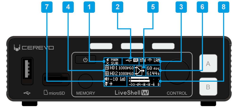
Power status pictogram
Indicates the power reception status of the two power inputs, MAIN and SUB. When power is being received, “⚡︎” is displayed; when power is not being received, “×” is displayed.
LiveShell Remote connection status pictogram
Indicates the connection status with the LiveShell Remote server. When connected, “☁” is displayed; when not connected, “×” is displayed. If you have not registered with LiveShell Remote, nothing is displayed.
Recording media connection status pictogram
Indicates the mount status of the USB drive and SD memory. When connected, the respective pictogram is displayed.
Network interface connection status pictogram
When the USB data communication terminal, wireless LAN adapter, or wired LAN port is connected, the respective pictogram is displayed.
HDMI input format display
Displays the HDMI reception format of input A and input B. When no connection can be detected, “NoInput” is displayed; when video in a format different from the system video format is being received, “BadFormt” is displayed.
Switcher status pictogram
Indicates which of Input A and Input B the switcher has selected.
Actual frame rate and actual bit rate display
Displays the frame rate and bit rate of the H.264 encoder output measured in real time.
Audio input status pictogram
The upper row displays the master level of the mixer. The lower row displays the mute status of the analog audio input as a pictogram.
Audio level meter
A meter that indicates the peak level of the audio signal measured at the mixer output.
How to use the screensaver
Unit menu / MAIN MENU →System →ScreensaverTime
LiveShell Studio / Not configurable
Factory default / OFF
This product is equipped with a screen saver.
This product’s unit display uses OLED. Due to the characteristics of OLED, screen burn-in may occur if the same screen is displayed for an extended period of time. To avoid this, the screen saver is recommended. When the screen saver is turned on, if the main UI is not used for a specified period of time, specific displays will be displayed up and down to prevent screen burn-in.
To make the setting, follow the steps below.
This operation can be performed from the main unit. It cannot be set with LiveShell Studio.
Please note that the screen saver setting will not work in the following cases:
When the home screen of a channel currently streaming or recording is displayed.
When any menu is displayed
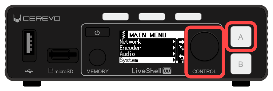
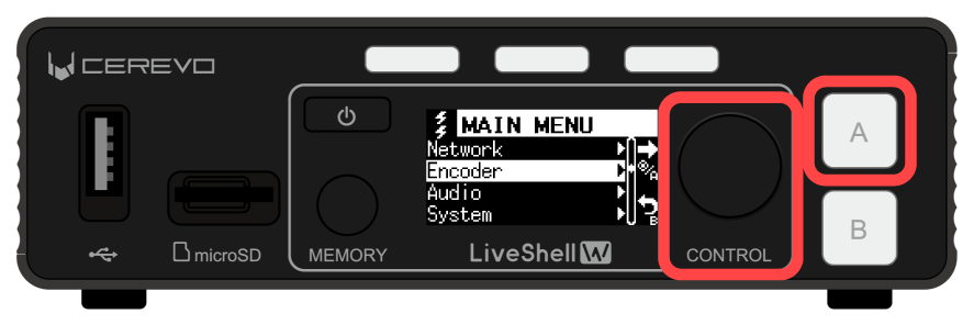
Press the control dial. When you press it, “MAIN MENU” is displayed.
Turn the control dial to select “System”, and press video select button A.
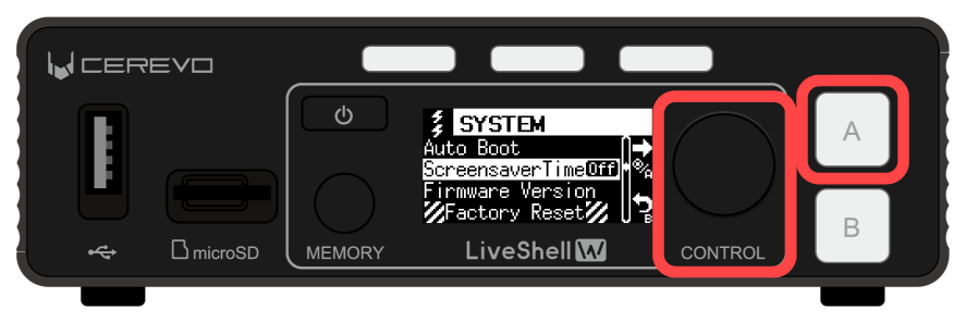
Turn the control dial to select “ScreensaverTime”, and press video select button A.
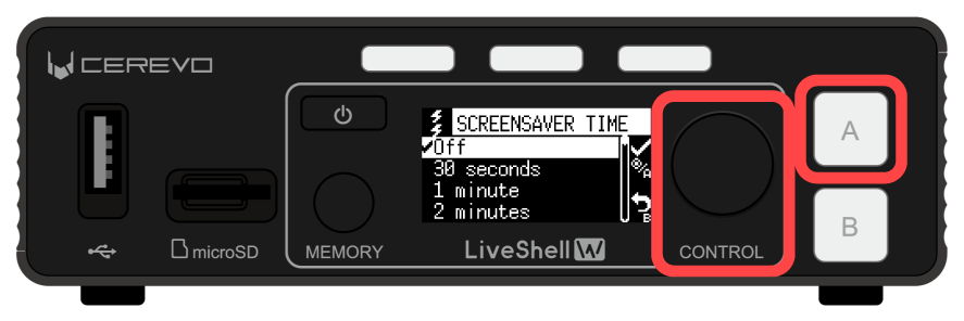
Turn the control dial to select the item you want to set, and press video select button A to apply the setting.
Network connection
Network requirements
To use this product, you need to connect this product to a network that meets the following requirements.
The network must be able to reach the Internet via IPv4, IPv6, or both.
Operation on a closed network is also possible, but the use of some functions may be restricted.
LiveShell Remote cannot be used on a closed network.
The IP address and other settings must be assignable by DHCP for IPv4 and by router advertisement for IPv6.
For IPv4 only, you can also set a fixed address manually.
There must be no obstruction to communication on at least the following ports.
80/tcp (used by the web application in this product)
1935/tcp (when using RTMP)
443/tcp (when using RTMPS)
443/tcp and 6275/tcp (when using LiveShell Remote)
554/tcp (standard port for the RTSP server in this product)
The destination IP address of the cloud server that provides the LiveShell Remote service is not disclosed. There are additional requirements when connecting to two types of networks at the same time or when using a mobile line. For details, please refer to the relevant sections.
Network connection patterns
The way this product connects to a network can be selected from the following patterns. Please select the applicable connection pattern according to the network environment you actually use.
Connecting via Wired LAN
This is a usage pattern in which this product is connected to a network via a wired LAN.
                                                              +-------------------+
                                                              |                   |
                                                              |                   |
                                                              | USB (not used)    |
                                              1000BASE-T      |                   |
                                          Local area network  |                   |
                                                    +---------| LAN               |
                                                    |         |                   |
                      +-------------------+         |         |                   |
                      |                   |         |         +-------------------+
                      |      Router       |---------+              LiveShell W
    The Internet <----|       with        |
                      |   switch ports    |---------+
  <-- Outgoing        |                   |         |         +-------------------+
  <-- RTMP stream     +-------------------+         +---------|    Web browser    |
                                                              +-------------------+
                                                          Laptop PC for LiveShell Studio
Connect the wired LAN port of the main unit (1000BASE-T Gigabit Ethernet interface) to an Ethernet switch or other device using an Ethernet cable.
At the factory default settings, no default IP address or other settings are configured for the interface; the IPv4 settings are obtained automatically by DHCP and the IPv6 settings by router advertisement. If you need to manually set the interface’s IP address and other settings on a network where DHCP or router advertisement is not available, use the wireless LAN access point mode to connect to LiveShell Studio and make those settings.
→Connecting to LiveShell Studio using wireless LAN access point mode
Connecting via Wireless LAN
This is a usage pattern in which this product is connected to a network via a wireless LAN. This product can only be connected in infrastructure mode.
                                                              +-------------------+
                                            802.11            |                   |
                                       Wireless network       |                   |
                                                       [WLAN]=| USB               |
                                                    ~~~~      |                   |
                      +-------------------+       ~~~~        |                   |
                      |                   |     ~~~~          | LAN (not used)    |
                      |      Router       |   ~~~~            |                   |
    The Internet <----|       with        | ~~~~              |                   |
                      |    Wireless AP    |   ~~~~            +-------------------+
  <-- Outgoing        |                   |     ~~~~              LiveShell W
  <-- RTMP stream     +-------------------+       ~~~~
                                                    ~~~~      +-------------------+
                                                      ~~~~    |    Web browser    |
                                                              +-------------------+
                                                          Laptop PC for LiveShell Studio
Connect a wireless LAN adapter to the USB port on the rear of the main unit, and connect to the wireless LAN network.
When using this product for the first time, or when connecting to a wireless network different from the one already configured in this product, you must first set the information of the wireless network to connect to (SSID and passphrase). This setting must be made by connecting to LiveShell Studio using a computer or similar device. To connect to LiveShell Studio, either connect this device to a network via wired LAN once, or use the wireless LAN access point mode to connect to LiveShell Studio, and make that setting.
→Connecting to LiveShell Studio using wireless LAN access point mode
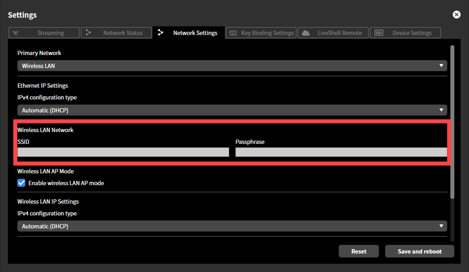
To configure the wireless LAN network, follow the steps below. This operation can be performed from LiveShell Studio. It cannot be set on the main unit.
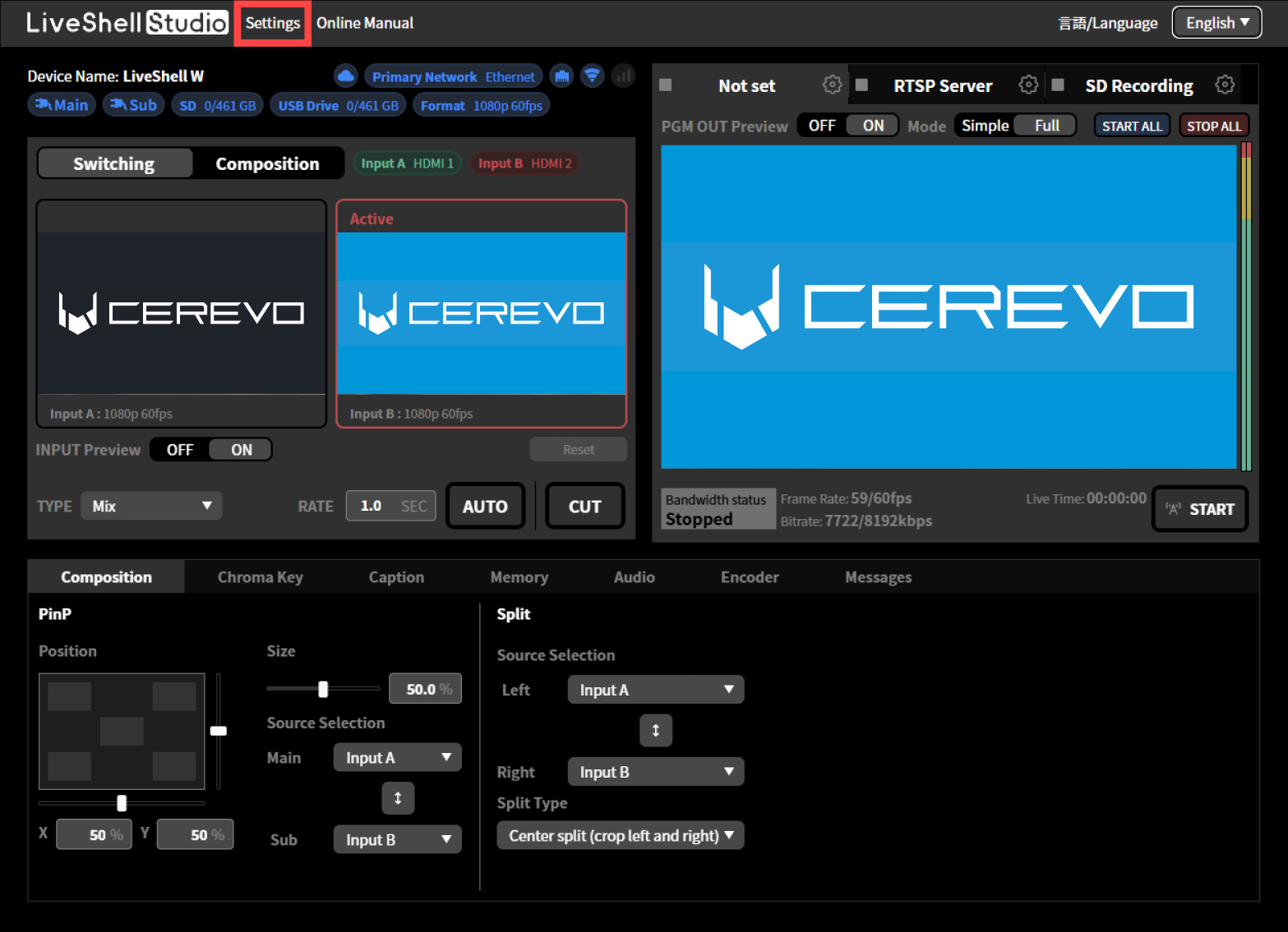
Press “Settings” displayed at the top of the top screen.
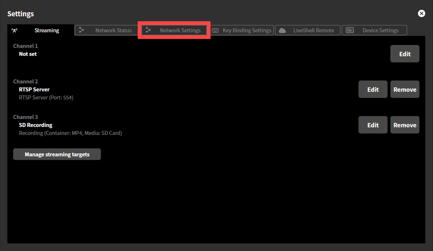
Press the “Network Settings” tab displayed at the top of the “Settings” screen.
From the pull-down menu displayed under “Preferred Network”, select “Wireless LAN”.
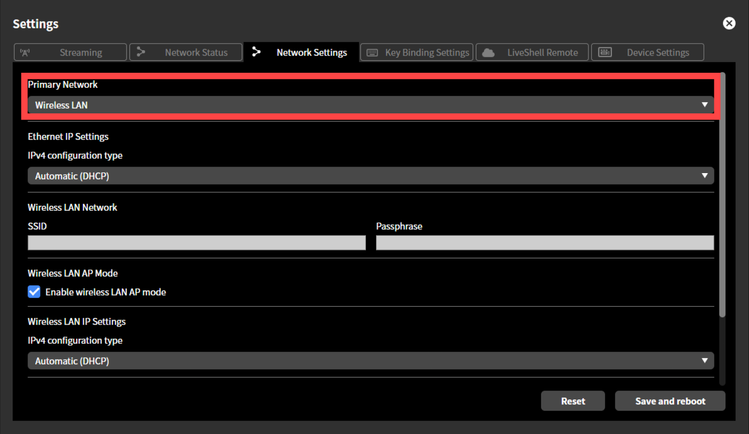
In “SSID” and “Passphrase” displayed under “Wireless LAN Network”, enter the SSID and passphrase (password) of the wireless LAN network to connect to, respectively.
Note that the SSID and passphrase entered here are not the ones displayed in “View AP Info”.
Press the “Enable wireless LAN AP mode” checkmark displayed under “Wireless LAN AP Mode” to clear the check.
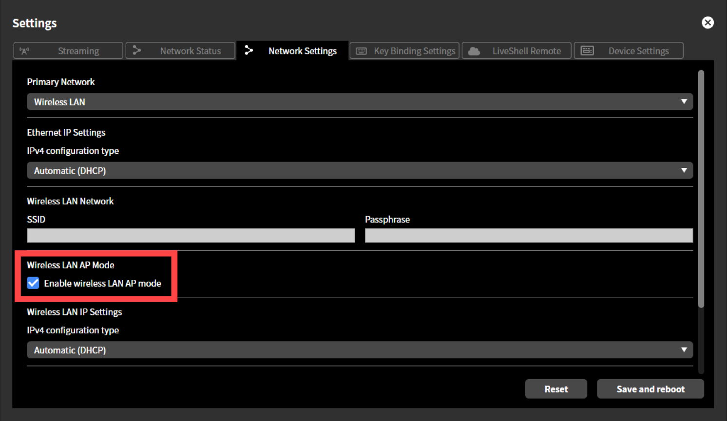
Press “Save and Restart”. This product restarts automatically.
Connecting using both wired LAN and wireless LAN
This product can use a wired LAN connection and a wireless LAN connection together. In this case, connect to the network according to the sections Connecting via Wired LAN and Connecting via Wireless LAN respectively, and then set the “Preferred Network” appropriately according to your usage pattern. The Preferred Network setting has the following effect on how the IPv4 default gateway is selected when communicating outside the IPv4 subnet to which this product is connected.
When the preferred network is wired LAN
The gateway reachable from the wired LAN interface is used preferentially, and the gateway reachable from the wireless LAN interface is used only when no gateway exists on the wired LAN interface. Normally, the wireless LAN interface side can communicate only with hosts within the same subnet. This setting is suitable for a usage pattern such as the one shown in the figure below.
Configuration example: Stream via wired LAN, and operate LiveShell Studio from a computer connected via wireless LAN
                                            <--- Monitoring Only Subnet --->

                                                              +-------------------+
                                                        ~~~~  |    Web browser    |
                      +-------------------+          ~~~~     +-------------------+
                      |                   |       ~~~~    Laptop PC for LiveShell Studio
                      |                   |    ~~~~
                      |  Wireless LAN AP  | ~~~~
                      |                   |   ~~~~
                      |                   |     ~~~~          +-------------------+
                      +-------------------+       ~~~~        |                   |
                                                    ~~~~      |                   |
                                                       [WLAN]=| USB               |
                                                              |                   |
                                                              |                   |
                                                    +---------| LAN (Primary)     |
  <-- Outgoing        +-------------------+         |         |                   |
  <-- RTMP stream     |                   |         |         |                   |
                      |                   |         |         +-------------------+
    The Internet <----|      Router       |---------+              LiveShell W
                      |                   |
                      |                   |
                      +-------------------+
                 Default gateway for LiveShell W

                                            <--- Production Subnet --->
When the preferred network is wireless LAN
The gateway reachable from the wireless LAN interface is used preferentially, and the gateway reachable from the wired LAN interface is used only when no gateway exists on the wireless LAN interface. Normally, the wired LAN interface side can communicate only with hosts within the same subnet. This setting is suitable for a usage pattern such as the one shown in the figure below.
Configuration example: Stream via wireless LAN, and operate LiveShell Studio from a computer connected via wired LAN
                                            <--- Production Subnet --->

  <-- Outgoing        +-------------------+
  <-- RTMP stream     |                   |
                      |      Router       |
    The Internet <----|       with        | ~~~~
                      |    Wireless AP    |   ~~~~
                      |                   |     ~~~~          +-------------------+
                      +-------------------+       ~~~~        |                   |
                 Default gateway for LiveShell W    ~~~~      |                   |
                                                       [WLAN]=| USB (Primary)     |
                                                              |                   |
                                                              |                   |
                                                    +---------| LAN               |
                                                    |         |                   |
                      +-------------------+         |         |                   |
                      |                   |         |         +-------------------+
                      |                   |---------+              LiveShell W
                      |    GbE Switch     |
                      |                   |---------+
                      |                   |         |         +-------------------+
                      +-------------------+         +---------|    Web browser    |
                                                              +-------------------+
                                                          Laptop PC for LiveShell Studio

                                            <--- Monitoring Only Subnet --->
Streaming using a USB data communication terminal
Unit menu / MAIN MENU →Network →Primary Net →Mobile, then select and confirm
LiveShell Studio / Settings →Network Settings →Priority network →Mobile →Save and Restart
By attaching a USB data communication terminal to the USB adapter port on the rear of the main unit, this product can connect and stream using a 4G mobile network.
Configuration example: Stream via a mobile network, and operate LiveShell Studio from a computer connected via wired LAN
                                            <--- Production Subnet --->

    The Internet <----[ 4G packet data network ]              +-------------------+
                                              ~~~~            |                   |
  <-- Outgoing                                  ~~~~          |                   |
  <-- RTMP stream                                  [4G modem]=| USB (Primary)     |
                                                              |                   |
                                                              |                   |
                                                    +---------| LAN               |
                                                    |         |                   |
                      +-------------------+         |         |                   |
                      |                   |         |         +-------------------+
                      |                   |---------+              LiveShell W
                      |    GbE Switch     |
                      |                   |---------+
                      |                   |         |         +-------------------+
                      +-------------------+         +---------|    Web browser    |
                                                              +-------------------+
                                                          Laptop PC for LiveShell Studio

                                            <--- Monitoring Only Subnet --->
Mobile network connection on this product has the following restrictions.
Operation with terminals other than those specified by us is not guaranteed.
Settings such as the APN cannot be configured from this product. In addition, the terminal’s status, such as signal strength, cannot be obtained.
Only streaming via RTMP or RTMPS is possible. The RTSP server cannot be used on a mobile network.
Because USB data terminals can communicate only via IPv4, the following requirements must be met.
In the streaming destination settings, IPv6 must not be specified as the communication protocol.
In the streaming destination settings, if the destination host specified by the RTMP URL is an FQDN, the following condition must be met.
At least one A record (IPv4 address) must be obtained during name resolution.
When the name resolution result also includes AAAA records (IPv6 addresses), explicitly specify IPv4 as the communication protocol.
In the streaming destination settings, when the destination host specified in the RTMP URL is an IP address, it must be an IPv4 address.
If you do not explicitly configure an IPv4 connection and the Ethernet connection has IPv6 connectivity, the streaming connection may be established via the Ethernet connection without using the mobile network.
To connect to the mobile network in this manner, follow the steps below. This operation can be performed from LiveShell Studio or from the main unit of this product.
Using LiveShell Studio
Connect the USB data communication terminal to a PC or other device in advance and complete the APN and other settings.
Before booting this product, connect the USB data communication terminal to the USB adapter port on the rear side of the main unit.
Boot this product.
Press “Settings” displayed at the top of the top screen.
Press the “Network Settings” tab displayed at the top of the “Settings” screen.
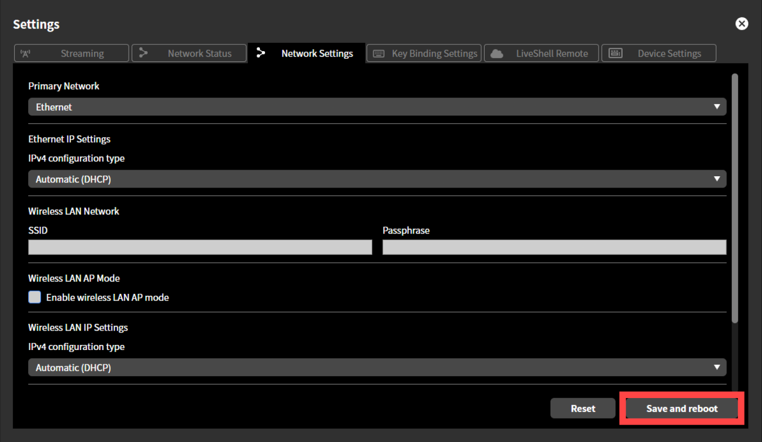
From the pull-down menu shown under “Primary Network”, select “Mobile”.
Press “Save and Restart”. This product restarts automatically.
Using the Main Unit
Connect the USB data communication terminal to a PC or other device in advance and complete the APN and other settings.
Before booting this product, connect the USB data communication terminal to the USB adapter port on the rear side of the main unit.
Boot this product.
Press the control dial. When you press it, “MAIN MENU” is displayed.
Turn the control dial to select “Network”, then press video select button A.

Turn the control dial to select “Primary Net”, then press video select button A.
Turn the control dial to select “Mobile”, then press video select button A.
Connecting to LiveShell Studio using wireless LAN access point mode
If this product cannot be connected to your existing network infrastructure via Ethernet or wireless LAN, you can use the wireless LAN access point mode to connect to LiveShell Studio.
What is a wireless LAN access point mode?
The wireless LAN access point mode is an operating mode in which this product’s wireless LAN adapter acts as a wireless LAN access point. By connecting a PC or other device used to operate this product as a terminal to the wireless LAN network provided by this access point, you can temporarily set up connectivity to operate this product even when its network settings have not been completed.
Operating conditions for the wireless LAN access point mode
To use the wireless LAN access point, this product must be booted with the wireless LAN adapter connected to the USB adapter port on the rear side of the main unit. Note that the wireless LAN access point mode and the function to connect this device to a wireless LAN network as a wireless LAN terminal (→Connecting via Wireless LAN) are mutually exclusive. Operating the wireless LAN access point mode does not affect Ethernet functionality.
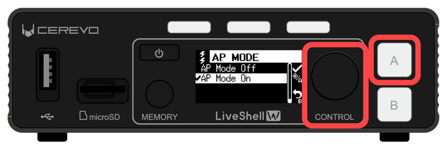
How to start the wireless LAN access point
Unit menu / MAIN MENU →Network →AP Mode →AP Mode On, then select and confirm
To start the wireless LAN access point of this product, follow the steps below. This operation can be performed from the main unit. It cannot be configured from LiveShell Studio.
Press the control dial. When you press it, “MAIN MENU” is displayed.
Turn the control dial to select “Network”, then press video select button A.
Turn the control dial to select “AP Mode”, then press video select button A.
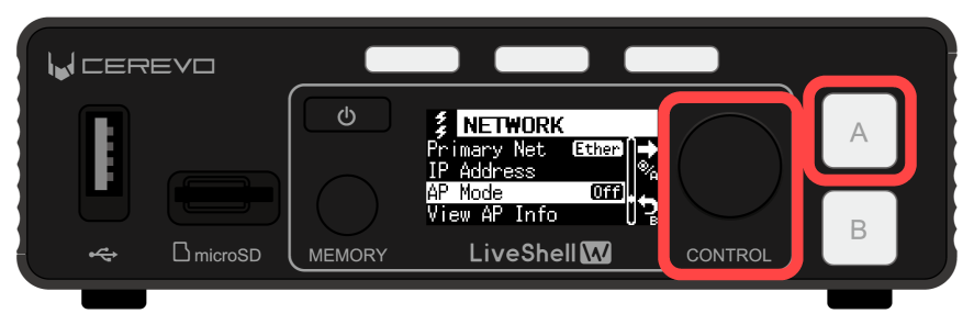
Turn the control dial to select “AP Mode On”, then press video select button A. The wireless LAN access point starts.
How to connect to the wireless LAN access point
Unit menu / MAIN MENU →Network →View AP Info
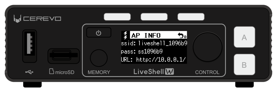
LiveShell Studio / Cannot be viewed
Using the SSID and password shown on this screen, you can configure the wireless LAN settings of your operating PC or other device and connect to this device via wireless LAN. After connecting to the wireless LAN network, an IPv4 address will be assigned to the terminal from the IPv4 subnet 10.0.0.0/24 space via DHCP. You can connect to LiveShell Studio from your web browser at http://10.0.0.1/.
To check the connection information for this product’s wireless LAN access point, follow the steps below. This operation can be performed from the main unit. It cannot be configured from LiveShell Studio.
Press the control dial. When you press it, “MAIN MENU” is displayed.
Turn the control dial to select “Network”, then press video select button A.
Turn the control dial to select “View AP Info”, then press video select button A.
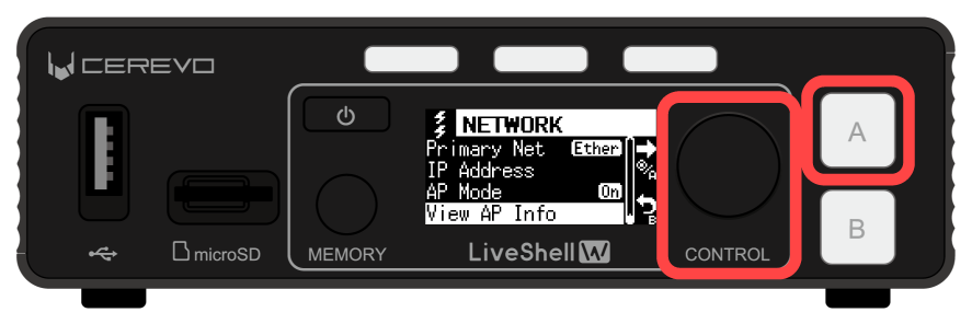
The information needed to temporarily connect this product and the operating terminal is displayed.
Connect to LiveShell Studio
About LiveShell Studio
LiveShell Studio is a web application for operation built into this product, and you can connect to it using the browser on a PC, tablet, or smartphone. Many of this product’s functions are designed to be operated using LiveShell Studio.
The following is an example of operations that can be performed using LiveShell Studio.
Settings
Setting the video resolution
Setting the encoder bitrate and other parameters
Network connection status and settings
Setting the video streaming destination
Setting the video composition method
Monitoring and operation
Previewing the video received on the HDMI inputs
Applying video composition and performing switching operations
Adjusting audio levels with the audio mixer
Starting and stopping streaming
How to connect to LiveShell Studio
The steps to connect to LiveShell Studio are as follows.
Confirm the URL to access LiveShell Studio
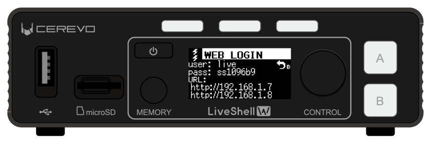
First, confirm the URL of LiveShell Studio and the user name and password for login from the menu on the main unit. The procedure is as follows.
Press the control dial. When you press it, “MAIN MENU” is displayed.
Turn the control dial to select “Network”, then press video select button A.
Turn the control dial to select “Web Login”, then press video select button A.
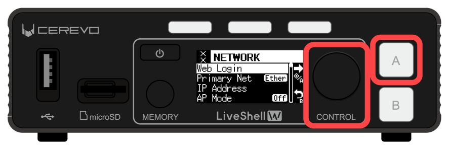
The information needed to access LiveShell Studio is displayed.
If this product’s network connection is not properly established, the URL will be blank. In this case, check that the network interface is configured correctly.
If for some reason this product cannot be connected to an existing network infrastructure, you can use the wireless LAN access point mode to connect an operating PC or other device.
→Connecting to LiveShell Studio using wireless LAN access point mode
Connecting to LiveShell Studio from a web browser
To connect to LiveShell Studio from a web browser, follow the steps below.
Connect an operating PC, tablet, smartphone, or other device (hereinafter referred to as the operating terminal) to the same subnet to which this product is connected.
Launch a web browser on the operating terminal, enter the URL shown on this product into the browser’s address bar, and access LiveShell Studio.
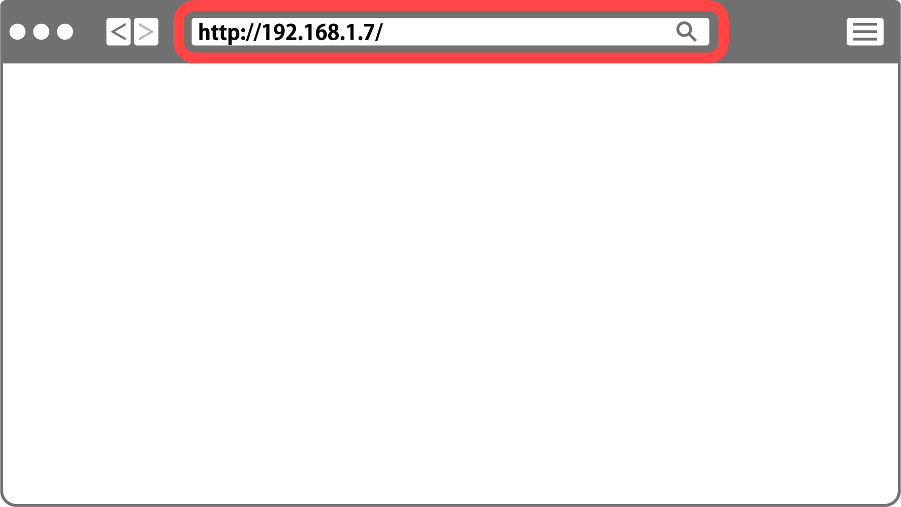
When you access it, you will be prompted to enter a user name and password. Enter the “user” and “pass” shown on this product respectively, and log in to LiveShell Studio.
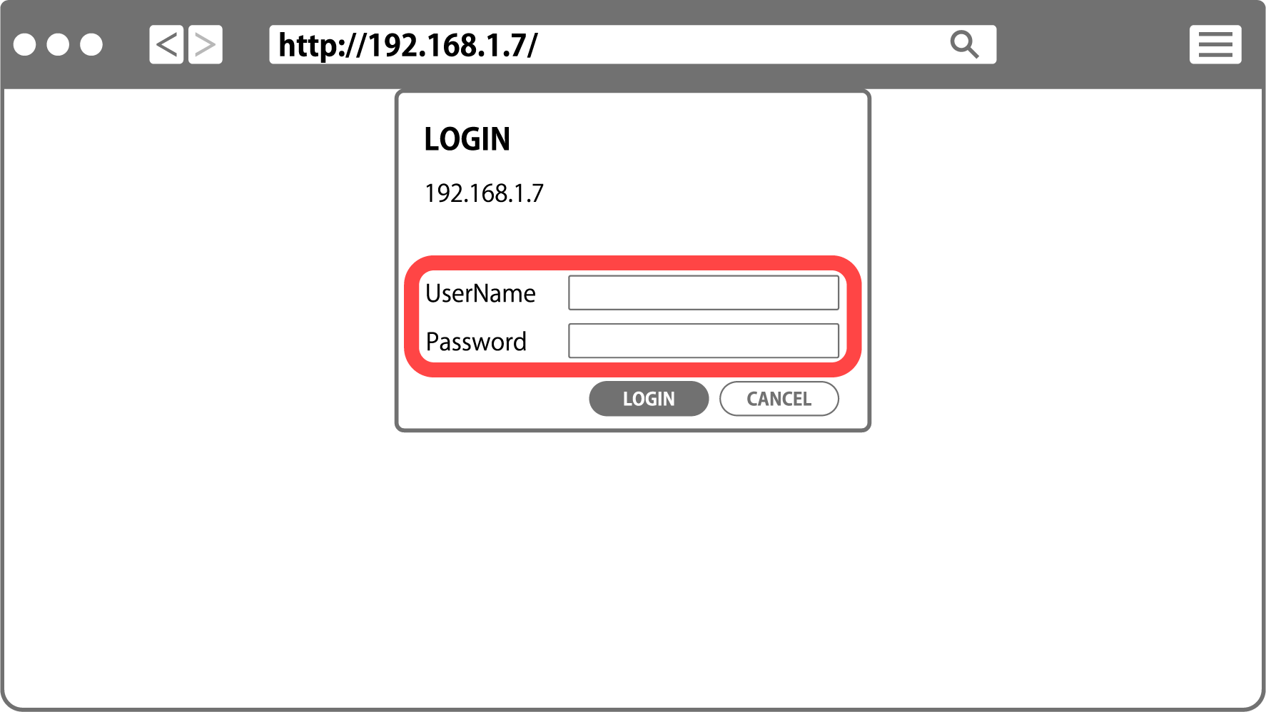
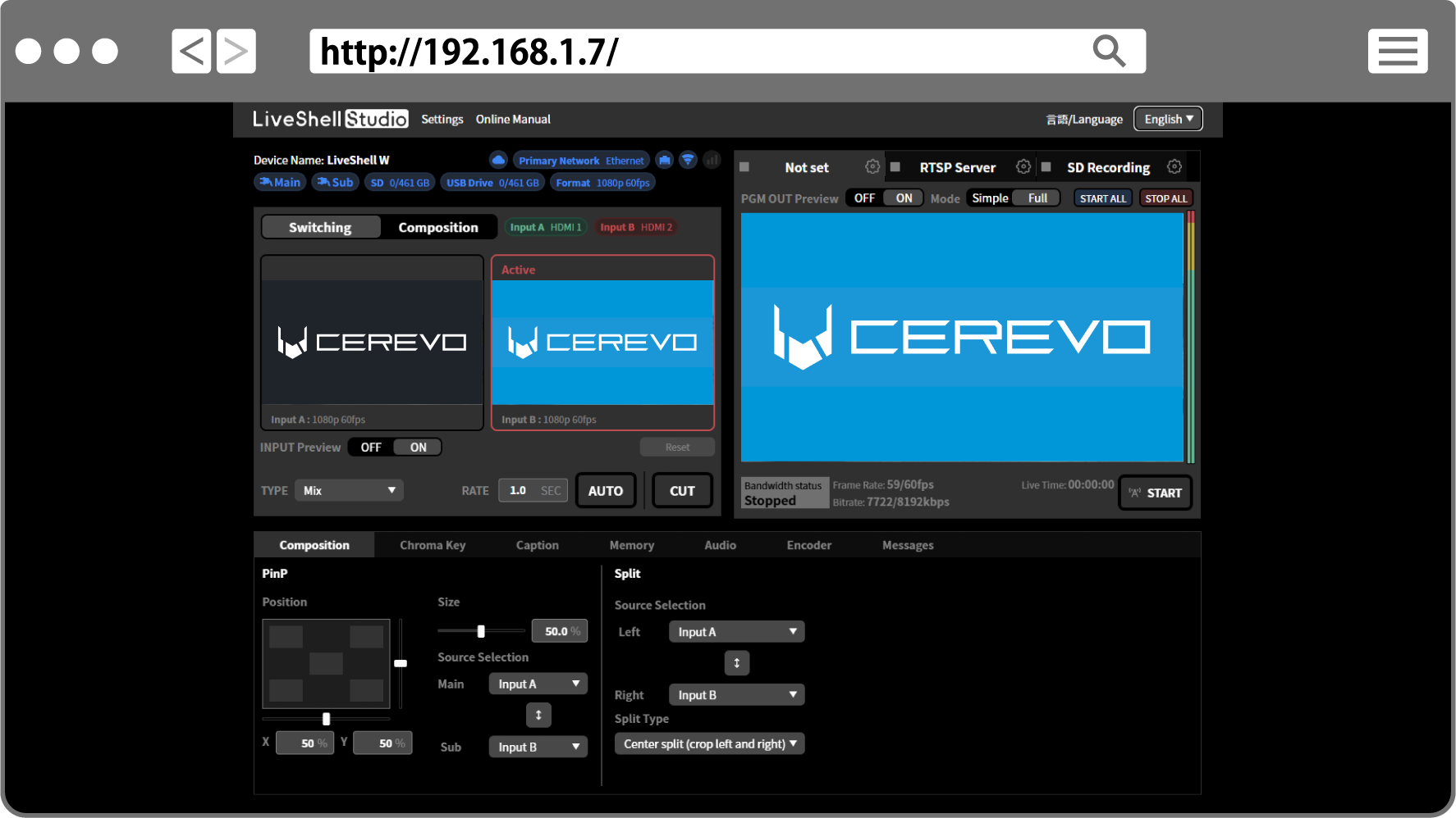
When login succeeds, the LiveShell Studio top screen is displayed in your web browser.
At first boot or after the main unit is initialized, Easy Setup starts automatically. If you want to configure settings using Easy Setup, proceed with the settings according to the displayed instructions. If you want to configure each item individually, select Skip.
Basic operations using LiveShell Studio
With LiveShell Studio, you can configure this product, perform live viewing of the input video, and operate video and audio. This section explains the basic operations.
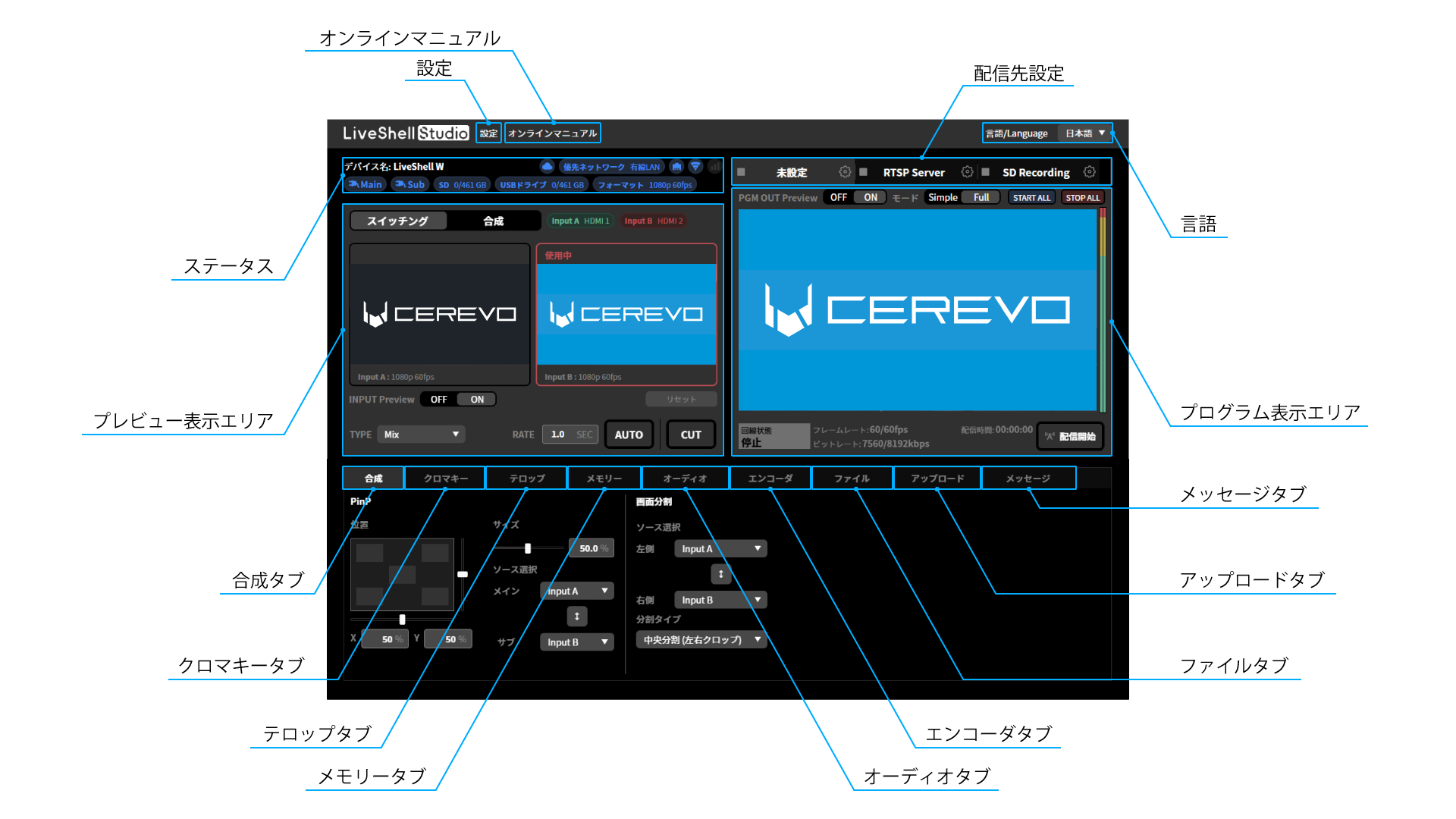
Configuring this product with LiveShell Studio (Settings)
When you click “Settings” at the upper left of the LiveShell Studio application screen, the settings screen for this product is displayed.
Viewing the online manual (Online Manual)
Displays the online manual for this product (this document).
Changing the display language of LiveShell Studio (Language)
From the “言語/Language” pull-down at the upper right of the LiveShell Studio application screen, you can switch the display language to either Japanese or English.
Checking the main unit status (Status)
Displays the current status of each channel. The displayed content is as follows:
Connection Status to LiveShell Remote
Displays the connection status to LiveShell Remote. If no connection is detected, it is grayed out.
Priority network
Displays the type of connection interface currently prioritized for use with the network.
Network type
Displays the type of connection interface currently connected to the network. If a connection cannot be detected, this will be grayed out.
Power status
Displays whether the power source, such as an AC adapter or power bank, is connected to the MAIN or SUB port. This will be grayed out if a connection cannot be detected.
Media connection status
Displays the mount status and remaining capacity of the SD card/USB drive. This will be grayed out if a connection cannot be detected.
System video format
Displays the system video format currently set on the main unit.
Live viewing of the input video (Preview display area)
The left half of the LiveShell Studio application screen is the “Preview display area”, where you can display thumbnails of the video received on the two HDMI inputs. In the preview area, you can also visually perform video switching, video composition settings, and more.
When you set the “INPUT Preview” switch to “ON”, thumbnails of the actual input video are displayed as live viewing of the input video. When set to “OFF”, live viewing stops, and the still images “A” and “B” are used as substitute images to represent the selected video.
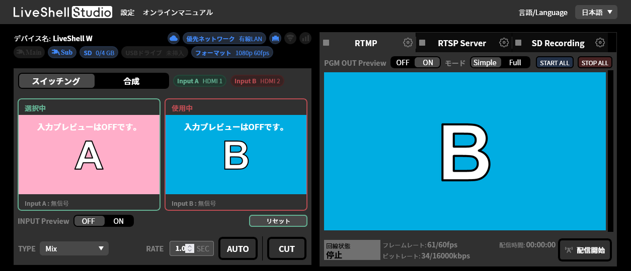
Live viewing of the program output (Program display area)
The right half of the LiveShell Studio application screen is the “Program display area”, where you can display the composited program output video in the “PGM OUT” area. In this area, you can also perform operations such as changing the network streaming destination settings and starting or stopping streaming.
When you set the “PGM OUT Preview” switch to “ON”, live viewing of the program output is displayed. When set to “OFF”, nothing is displayed. In addition, using the “Mode” switch, you can select the rendering method for live viewing from either “Simple” or “Full”.
When “Mode” is “Simple”, a simulated composite video is displayed using the live viewing video of the input. When the “INPUT Preview” switch is “OFF” and live viewing of the input video is stopped, the substitute images “A” and “B” are used for the composition.
When “Mode” is “Full”, the same stream as the one being streamed is acquired and played back. In this mode, you can also monitor the audio, but audio playback does not start automatically. You can check the audio by unmuting it in the browser (the method for unmuting varies by browser, but can generally be done by right-clicking to display the controls).
Limitations of live viewing
The video displayed as live view has the following limitations.
If signal reception from HDMI is interrupted, the thumbnail on the preview screen continues to display the last frame shown. Also, if the HDMI format recognition does not match the video reception state, the thumbnail may not be displayed correctly. This does not apply when “INPUT Preview” is OFF.
When “Full” is selected as the live viewing mode for the program output, the video and audio are generated by playing back the same stream as the one being streamed, so there is a delay compared to the input video thumbnails. There is also a discrepancy with the movement of the audio level meters.
When “Simple” is selected as the live viewing mode for the program output, the video uses the thumbnail images used on the preview screen and uses a simulated composite result. This simulated video has the following limitations.
It does not exactly match the actual program output.
Video effects such as Mix and wipe are not reproduced.
Chroma key is not reproduced.
No audio is output.
On Safari and iOS browsers, live viewing of the program output in “Full” mode is not available.
The default state of live viewing for both the input video and the program output is “ON”. However, when you connect to LiveShell Studio via LiveShell Remote, the default state is “OFF”.
For the purpose of monitoring the program output, you can also use the monitor output (→Connecting a video monitor output) or the RTSP server function.
Streaming/recording target settings (Stream Target settings)
You can configure the streaming and recording settings for each channel.
Detailed operations for video and audio
At the bottom of the Preview screen and the Program screen there is an “operations area”, which is divided into tabs for each function, such as “Composition”, “Caption”, “Audio”, and “Encoder”. Pressing these tabs displays the interface for performing detailed operations related to each item. In addition, pressing the “Messages” tab displays messages about operations.
→How to operate the audio mixer
Composition tab
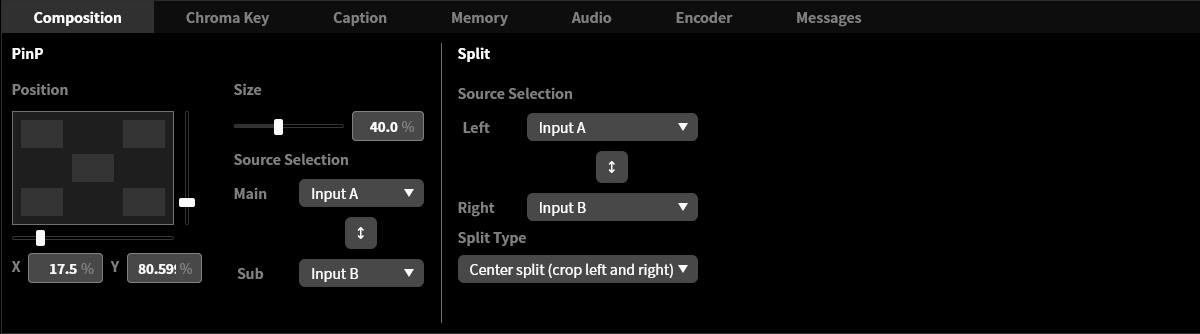
You can configure settings related to video composition.
Chroma key tab
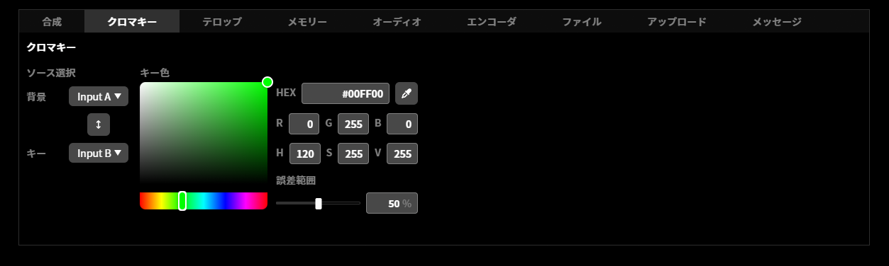
You can configure settings related to chroma key.
Caption tab
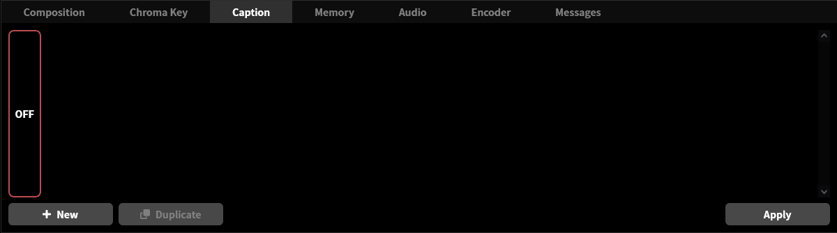
You can configure settings related to captions.
Memory tab
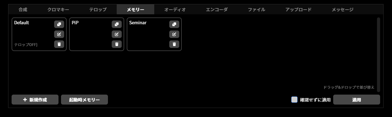
You can configure settings related to the Memory function.
Audio tab
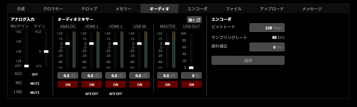
You can configure settings related to audio.
Encoder tab
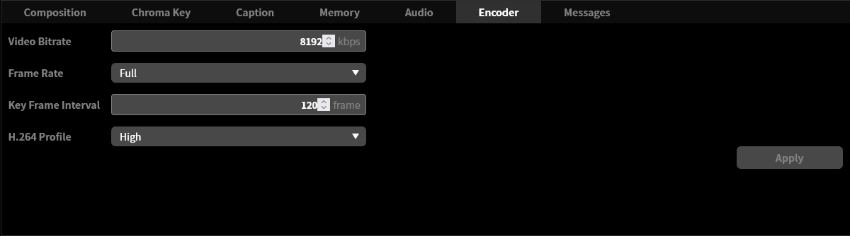
You can configure settings related to the video encoder.
File tab
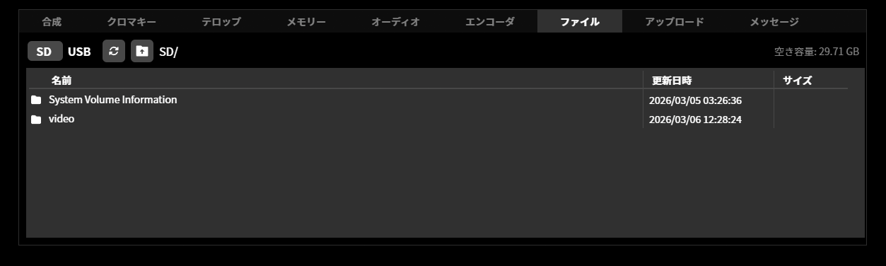
You can perform operations on files in the recording media connected to the device.
Upload tab
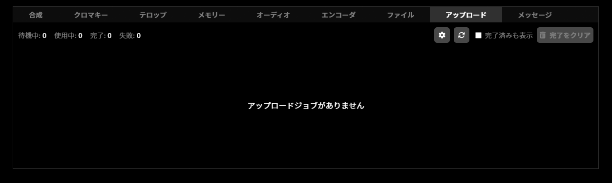
You can perform operations related to uploading files in the recording media connected to the device.
Messages tab
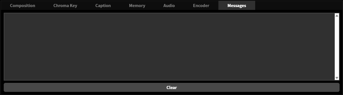
Messages about the operation currently being performed and error messages are displayed.
Remote operation using LiveShell Remote
LiveShell Remote is a cloud service that connects to the LiveShell Studio of this product over the Internet to operate the device remotely. It can be used in cases such as when the location where this product is installed is far from the location where it is operated, or when this product is maintained or operated remotely.
Service agreement for the LiveShell Remote service
To use LiveShell Remote, you must purchase a service agreement and license. Please confirm the service details on the service website below before purchasing the agreement and license.
Registering a device with LiveShell Remote
After purchasing a license, you need to register the device you want to operate using LiveShell Remote with the cloud. First, connect to LiveShell Studio via wired LAN, wireless LAN, or AP mode, and select “LiveShell Remote” in the settings menu.
Enter the PIN code provided with your LiveShell Remote license in the “Register this device with LiveShell Remote” field, and press the “Register” button to register.
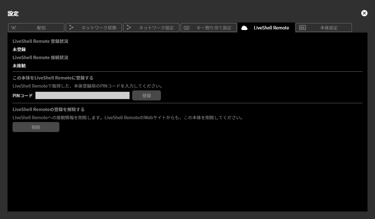
When registration is successful, the “LiveShell Remote registration status” becomes “Registered” and the device ID is displayed.
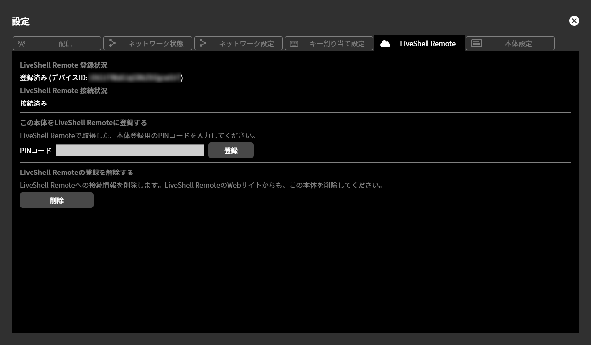
Unregistering from LiveShell Remote
For a device registered with LiveShell Remote, if you want to suspend the use of LiveShell Remote, perform “Delete” in “Unregister from LiveShell Remote”. Once unregistered, operations using LiveShell Remote will no longer be possible until the device is registered again. Note that unregistering does not delete the LiveShell Remote license.
Connection to the LiveShell Remote server
A device registered with LiveShell Remote automatically connects to the LiveShell Remote cloud server over the Internet. If a connection to the server cannot be established due to network outage or similar, the device will periodically retry the connection. For how to check the connection status with the cloud server, see the next section.
Checking the LiveShell Remote connection status
You can check the connection status between this product and the LiveShell Remote cloud server from LiveShell Studio or the main status screen on this product’s OLED display.
In the LiveShell Studio web application, when this product is correctly connected to the LiveShell Remote cloud server, the ☁ (cloud-shaped) icon is displayed in blue. When the device is registered but a connection to the cloud server has not been established, the ☁ is displayed in red with a slash through it. For a device that is not registered with LiveShell Remote, the ☁ is displayed in gray with a slash through it. In addition, pressing the ☁ icon lets you check the registration status with LiveShell Remote, the device ID, and the connection status with the cloud server.
On the device’s main status screen, the ☁ (cloud-shaped) icon is displayed when this product is correctly connected to the LiveShell Remote cloud server. When the device is registered but a connection to the cloud server has not been established, an × icon is displayed in the corresponding location. For a device that is not registered with LiveShell Remote, nothing is displayed. In addition, you can check the device ID and connection status from the device menu / MAIN MENU →Network →Remote Status.
If a connection to the cloud server cannot be established and you are retrying the connection, a ☁ (cloud) icon may briefly appear to indicate the connection status.
Easy Setup
Unit menu / Not configurable
LiveShell Studio / Settings → Device Settings → Run Easy Setup
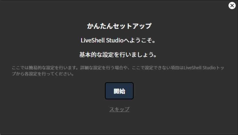
This product includes an “Easy Setup” wizard for performing configuration in a simple way. On the first startup or after the device has been initialized, Easy Setup starts automatically.
To make the setting, follow the steps below.
This operation can be performed from LiveShell Studio. It cannot be performed on the device itself.
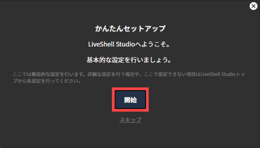
Operation when Easy Setup starts automatically
Press “Start” in the displayed dialog. If you do not want to perform the configuration, press “Skip” or the “✕” button at the top right to close the dialog.
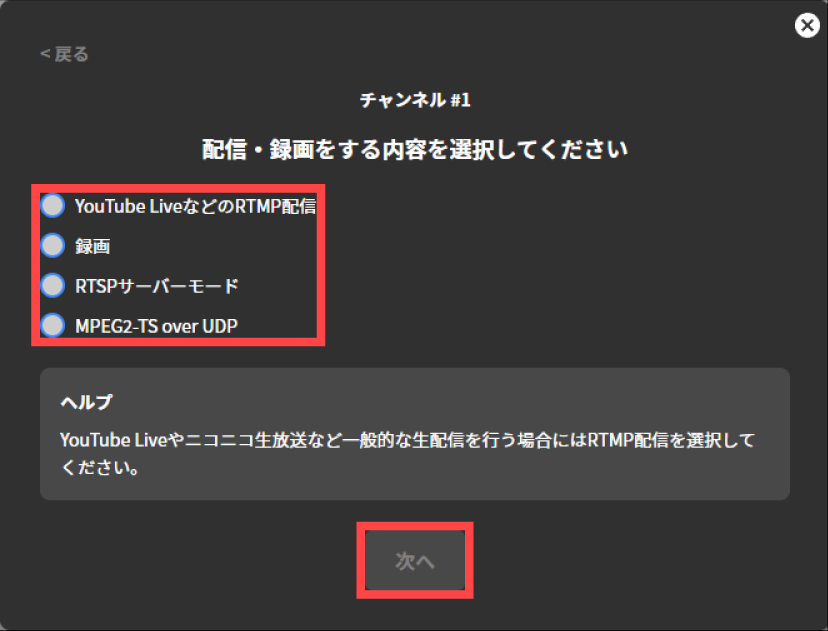
Select what to record and stream on Channel #1, and press “Next”.
Enter the desired values in the input fields for each displayed setting. The setting values to enter differ depending on the stream target type. Refer to the respective procedures below. Once you have completed each entry, press “Next”.
→Live streaming recording destination setting
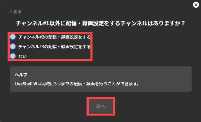
If you also want to configure streaming/recording settings for Channel #2 and Channel #3, select “Configure streaming/recording settings for Channel #2” or “Configure streaming/recording settings for Channel #3” and press “Next”. The configuration method is the same as before. To finish the streaming/recording settings and proceed to the next setting, select “No” and then press “Next”.
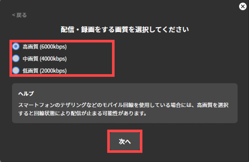
Select the video quality for streaming and recording, and press “Next”.
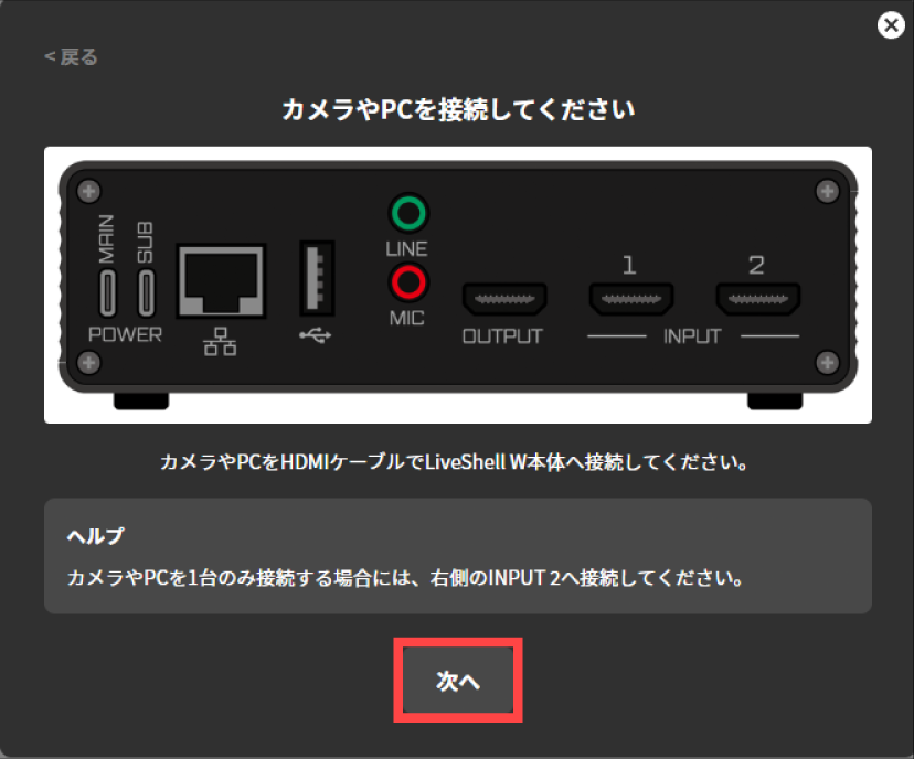
Following the instructions on the displayed screen, connect your camera or PC to the LiveShell W device with an HDMI cable. If you connect only one camera or PC, connect it to INPUT2 on the right side.
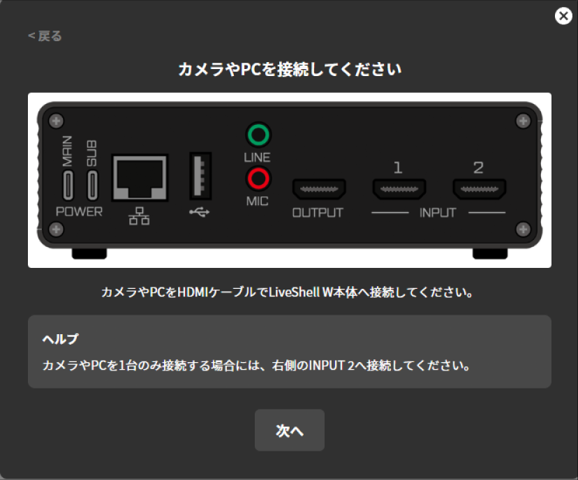
Once the connection is complete, press “Next”.
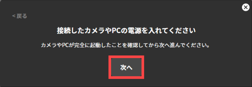
Following the instructions on the displayed screen, turn on the power of the connected camera or PC.
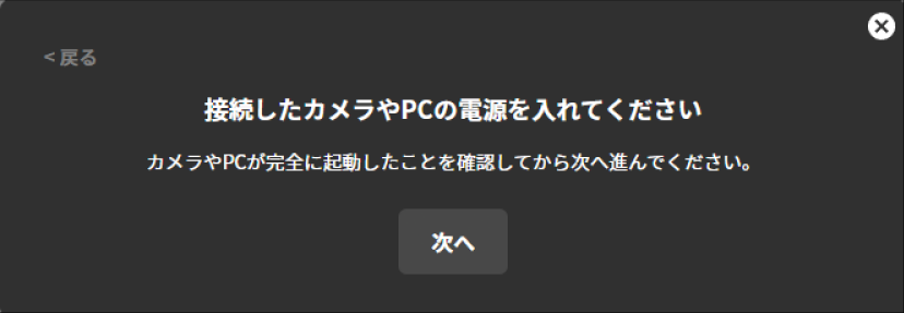
After confirming that the connected camera or PC has fully started up, press “Next”.
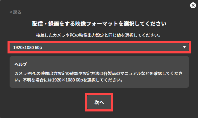
Select the video format for streaming and recording, and press “Next”. Here, select the same value as the video output setting of the connected camera or PC.
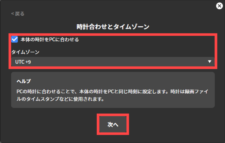
Configure the clock and time zone of the LiveShell W device. If you check “Sync the device clock with the PC”, the LiveShell W device’s clock can be set to the same time as the PC’s clock. If you use it in Japan, select “UTC +9” for “Time Zone”.
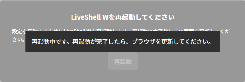
Restart the LiveShell W device. Pressing “Restart” automatically restarts the LiveShell W device.
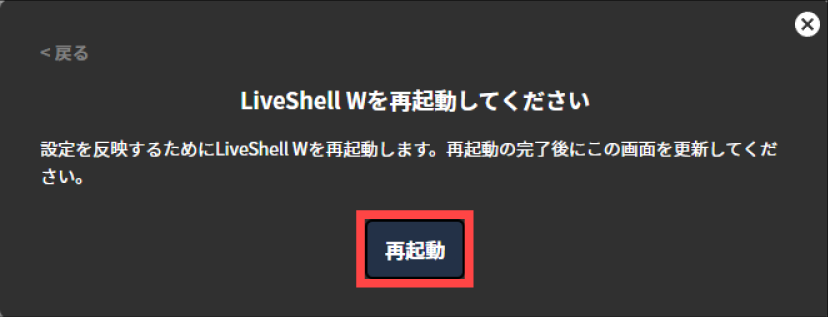
Once the LiveShell W device has finished restarting, refresh your browser.
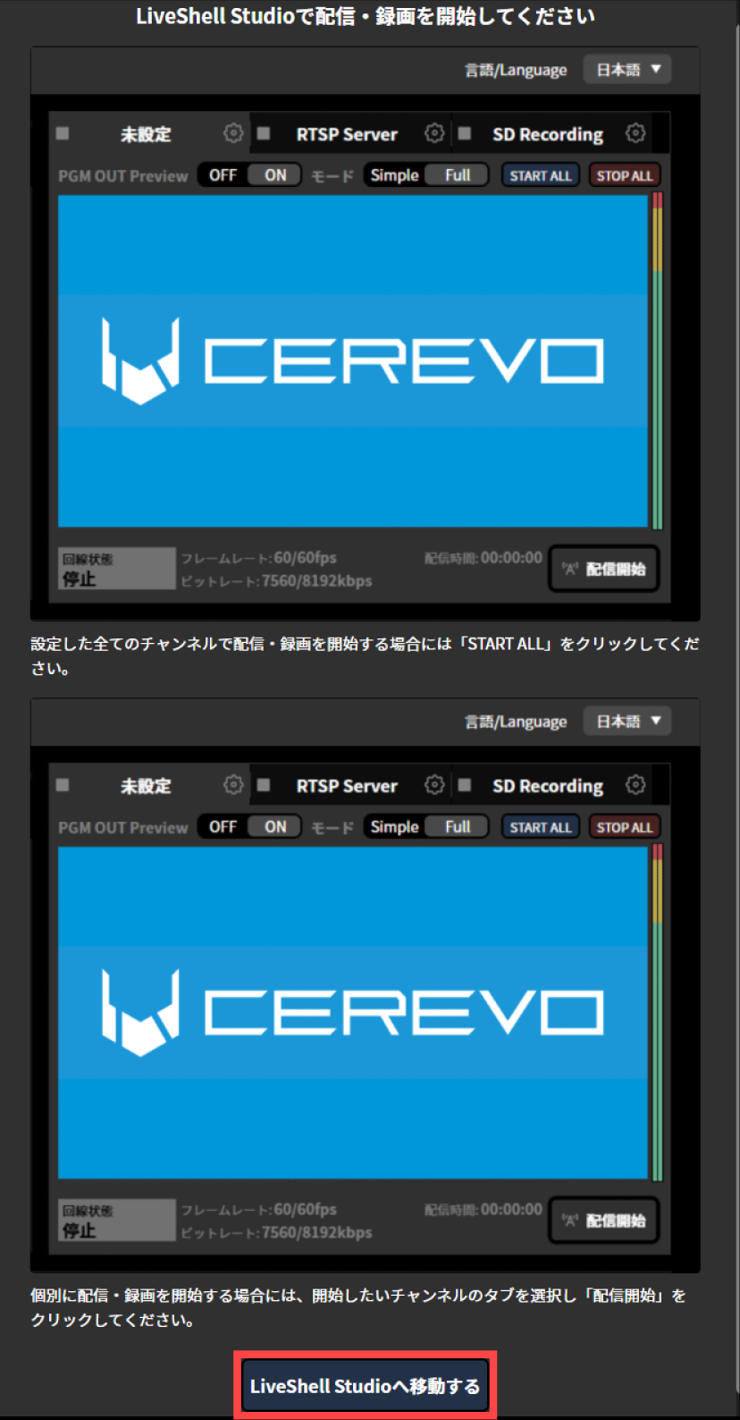
The following screen is displayed automatically. Following the instructions on the displayed screen, go to LiveShell Studio and then start streaming. Pressing “Go to LiveShell Studio” takes you to the LiveShell Studio top screen.
RTMP streaming settings
For the RTMP streaming settings, you need to configure the following items.

In “Display Name”, enter any name that is easy to manage. It is not reflected in the stream target.
In “RTMP URL,” enter the RTMP URL obtained from the live streaming platform.
In “Stream Key,” enter the stream key obtained from the live streaming platform.
Live streaming recording destination setting
To configure the recording settings, follow the steps below.
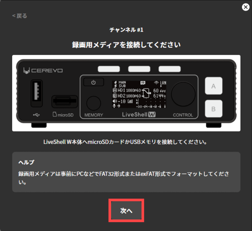
Following the instructions on the displayed screen, connect recording media to the LiveShell W device.
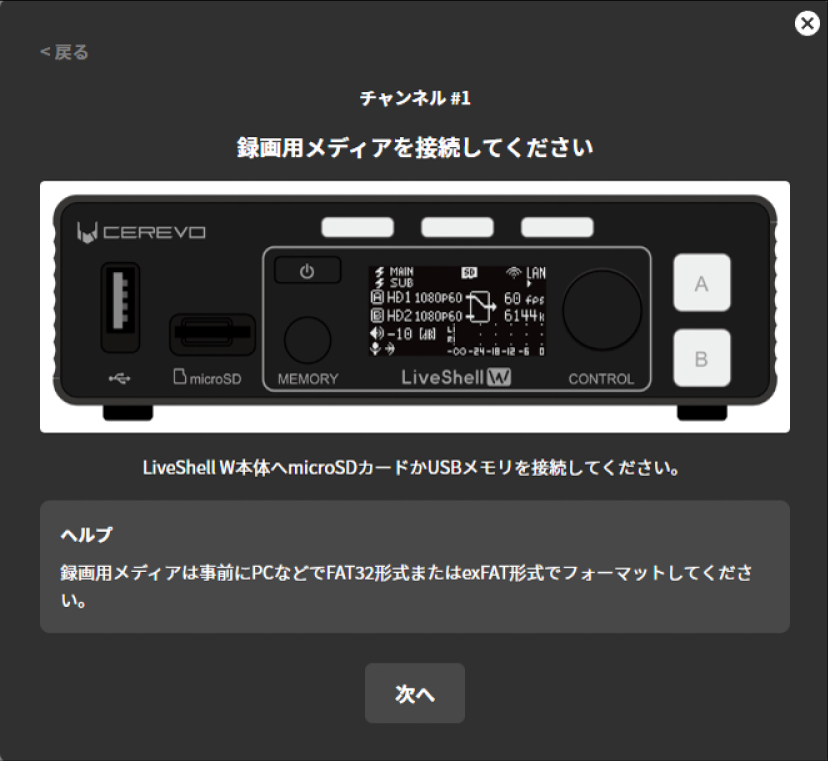
Once the connection is complete, press “Next”.
For the recording settings, you need to configure the following items.
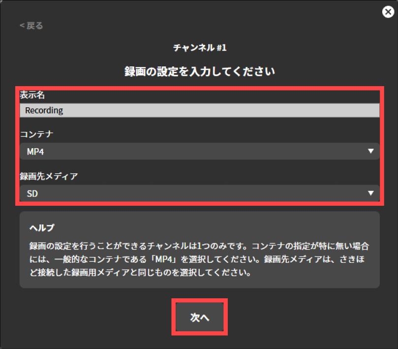
In “Display Name”, enter any name that is easy to manage. It is not reflected in the stream target.
In “Container,” specify the container format to use when saving the stream. Choose either “MP4” or “MPEG2-TS.”
In “Destination Media,” specify the recording media to record to. You can choose either “SD Card” or “USB Drive.”
RTSP server setting
For the RTSP server settings, you need to configure the following items.
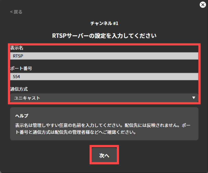
In “Display Name”, enter any name that is easy to manage. It is not reflected in the stream target.
In “Port number”, enter the TCP port on which the RTSP server listens. Normally, this should be “554”.
In “Communication method”, select whether to send media packets via unicast or multicast. Normally, select “Unicast”.
If you select multicast, enter the Time To Live value for multicast distribution in “Multicast TTL”.In “Communication protocol”, specify the network layer protocol. You can specify Unspecified, IPv4 only, or IPv6 only. Normally, select “Unspecified”.
MPEG2-TS over UDP setting
For MPEG2-TS over UDP, the following items must be configured.
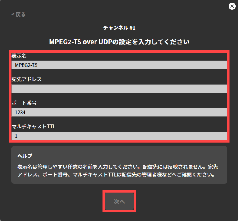
In “Display Name”, enter any name that is easy to manage. It is not reflected on the streaming target.
In “Destination Address,” enter the destination IP address to which the UDP datagram will be sent.
In “Port Number,” enter the destination port number for the UDP datagram to be sent.
In “Multicast TTL,” enter the Time To Live value for multicast distribution.
Operation when launched from the settings dialog
Press “Settings” displayed at the top of the top screen.
Press the “Device Settings” tab displayed at the top of the “Settings” screen.
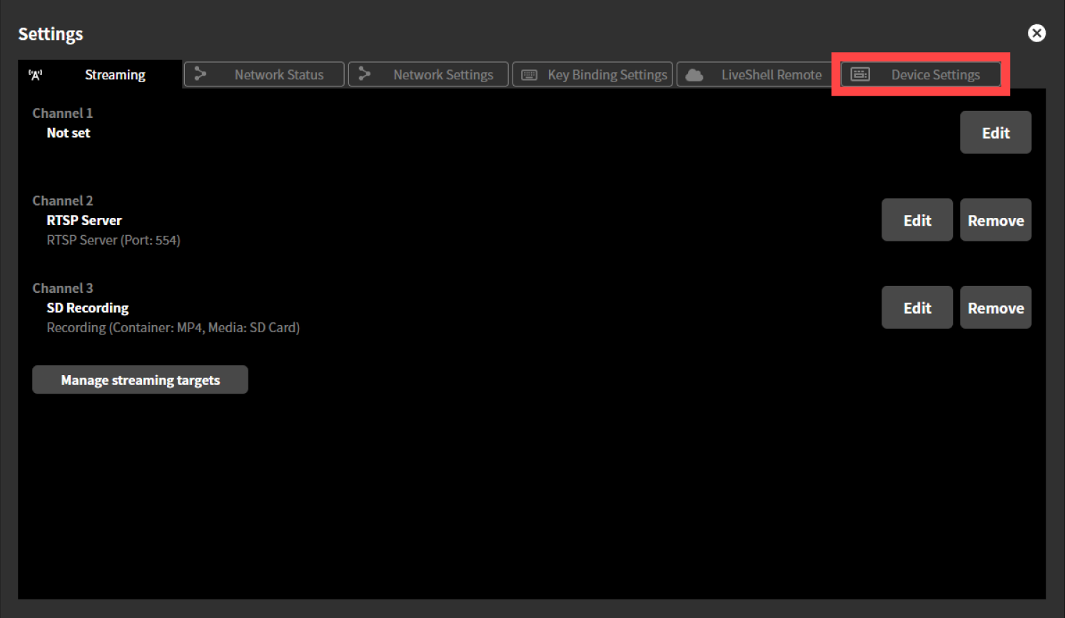
Press “Run Easy Setup” displayed in “Easy Setup”.
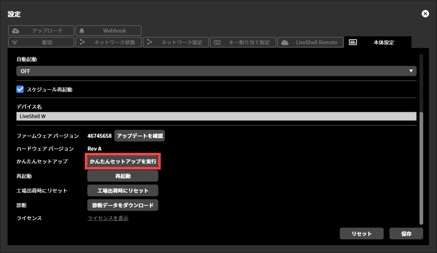
Easy Setup will launch. For the subsequent steps, refer to Operation when Easy Setup starts automatically.
System settings
This section describes the initial settings to be performed first.
System video format
Unit menu / MAIN MENU →Encoder →Resolution
LiveShell Studio / Settings →Device Settings tab →System video format
Factory default / 1920x1080 60p
“System Video Format” is used to determine the format (number of pixels, frame rate, and whether interlaced or not) of the video signal input to this product. The system video format can be selected from one of the following.
1920x1080 60p
1920x1080 50p
1920x1080 30p/60i
1920x1080 25p/50i
1920x1080 24p
1280x720 60p
1280x720 50p
1280x720 30p
1280x720 25p
1280x720 24p
720x576 24p
720x480 60p
640x480 60p
The format of the video input to the HDMI INPUT 1 and HDMI INPUT 2 terminals must match the system video format setting. Inputting video in a format different from the system video format may cause problems such as the video not being recognized or not being played back correctly. Be sure to check that they match.
When 1920×1080 30p/60i or 1920×1080 25p/50i is selected as the system video format, interlaced video can be input. When interlaced video is input, this product performs de-interlacing from 60i to 30p and from 50i to 25p, and treats it as progressive video equivalent to half the frame rate of the original video.
The resolution and frame rate of the stream output by the video encoder are also the same as the system video format. If the system video format is changed while this product is operating, the streamed video may be disturbed. In this case, please reboot the product.
To configure the system video format, follow the steps below. This operation can be performed from LiveShell Studio or from the main unit of this product.
Using LiveShell Studio
Press “Settings” displayed at the top of the top screen.
Press the “Device Settings” tab displayed at the top of the “Settings” screen.
From the pull-down menu displayed in “System Video Format”, select the desired value you want to set.
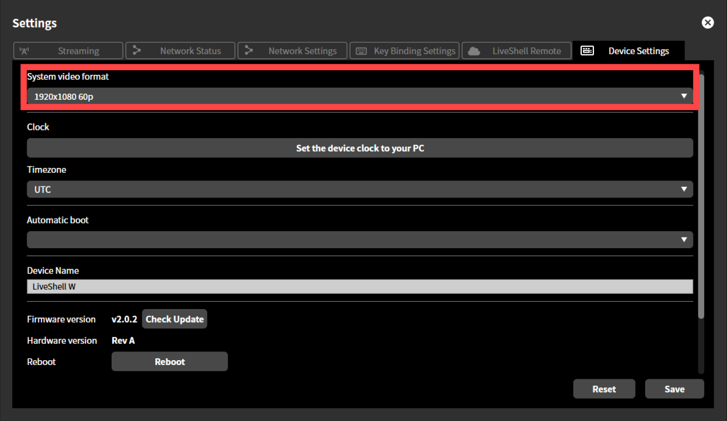
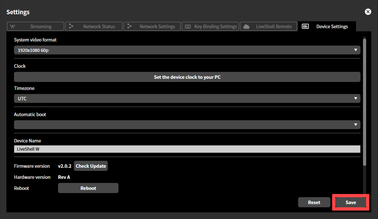
Pressing the “Save” button applies the setting.
Reboot this product.
Using the Main Unit
Press the control dial. When you press it, “MAIN MENU” is displayed.
Turn the control dial to select “Encoder”, and press video select button A.
Turn the control dial, select “SysVideoFmt” and push Video select button A on the front of this product.
Operate each displayed setting in the same way as above, and set the desired value.
If you set it on the main unit, select the desired value in each input field. The setting will be applied when you press the Video select button A.
Reboot this product.
Clock setting
Unit menu / Not configurable
LiveShell Studio / Settings →Device Settings tab →Clock
Factory default / None
This function is used to manually set the date and time of the clock built into this product. When you press the “Set the device clock to your PC” button, this product’s clock is set to the same date and time as the clock of the PC or other device running the browser. In addition to this method, this product’s clock can also be synchronized with an NTP server using the Network Time Protocol.
The time set here will appear on the unit’s display.
To set up a name, follow the steps below.
This operation can be performed from LiveShell Studio. It cannot be set on the unit button operation.
Press “Settings” displayed at the top of the top screen.
Press the “Device Settings” tab displayed at the top of the “Settings” screen.
Press “Set the device clock to your PC”.
A dialog appears. Press “OK” to close the dialog.
Time zone setting
Unit menu / Not configurable
LiveShell Studio / Settings →Device Settings tab →Time zone
Factory default / UTC
This sets the time zone for the clock built into this product.
To set up a name, follow the steps below.
This operation can be performed from LiveShell Studio. It cannot be set on the unit button operation.
Press “Settings” displayed at the top of the top screen.
Press the “Device Settings” tab displayed at the top of the “Settings” screen.
From the pull-down menu displayed in “Time zone”, select the desired value you want to set.
Pressing the “Save” button applies the setting.
Automatic boot
Unit menu / MAIN MENU →System →Auto Boot
LiveShell Studio / Settings →Device Settings tab →Auto boot
Factory default / OFF
This setting determines whether this product boots automatically when a power supply is connected to it. When automatic boot is set to ON, the product starts up even without operating the power button. When automatic boot is set to OFF, the product does not start up merely by connecting a power supply, but boots after the power button is operated.
To make the setting, follow the steps below.
This operation can be performed from LiveShell Studio or from the main unit of this product.
Using LiveShell Studio
Press “Settings” displayed at the top of the top screen.
Press the “Device Settings” tab displayed at the top of the “Settings” screen.
From the pull-down menu displayed in “Automatic boot”, select “ON”.
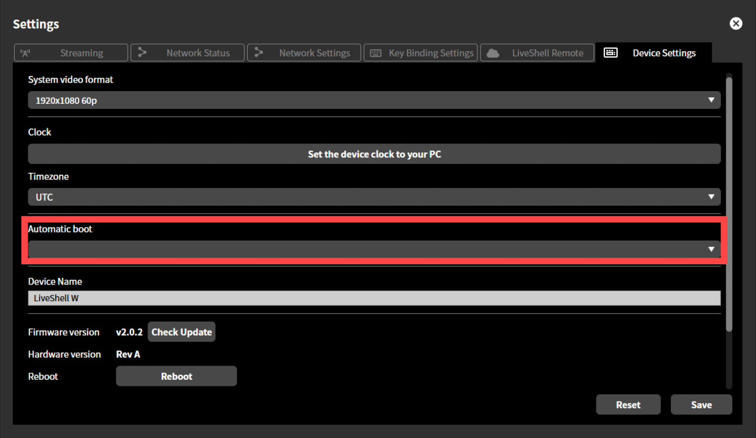
Pressing the “Save” button applies the setting.
Using the Main Unit
Press the control dial. When you press it, “MAIN MENU” is displayed.
Turn the control dial to select “System”, and press video select button A.
Turn the control dial to select “Automatic Boot” and press the Picture Select Button A.
Turn the control dial to select “On” and press the Picture Select Button A to apply the setting.
Scheduled reboot
Unit menu / Not configurable
LiveShell Studio / Settings →Device Settings tab →Scheduled restart
Factory default / OFF
This setting automatically reboots this product at a specific time that you set. When scheduled reboot is set to ON, the product reboots automatically according to the configured schedule. The reboot is performed even during streaming.
The selectable settings are as follows.
Schedule type
Daily
Weekly
Monthly
Reboot time
00:00 to 23:59
To set up a name, follow the steps below.
This operation can be performed from LiveShell Studio. It cannot be set on the unit button operation.
Press “Settings” displayed at the top of the top screen.
Press the “Device Settings” tab displayed at the top of the “Settings” screen.
Check “Scheduled reboot”.
From the pull-down menu displayed in “Scheduled reboot”, select the desired value you want to set.
Pressing the “Save” button applies the setting.
Device name setting
Unit menu / Not configurable
LiveShell Studio / Settings →Device Settings tab →Device name
Factory default / LiveShell W
The device name is an arbitrary name that can be assigned to an individual unit of this product. The value set here is only displayed on the banner of LiveShell Studio, and whatever value is set has no effect on operation. One possible use is to set a name that makes units easy to distinguish when handling multiple units at the same time. The initial value is set to “LiveShell W”.
To make the setting, follow the steps below.
This operation can be performed from LiveShell Studio. It cannot be configured on the main unit.
Press “Settings” displayed at the top of the top screen.
Press the “Device Settings” tab displayed at the top of the “Settings” screen.
Enter any display name in the text box in “Device name”.
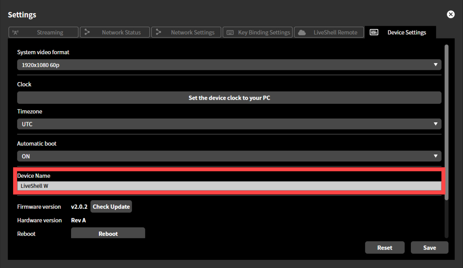
Pressing the “Save” button applies the setting.
Network settings
Network primary setting
Unit menu / MAIN MENU →Network →Primary Net
LiveShell Studio / Settings →Network Settings tab →Priority network
Factory default / Wired LAN
The network primary setting determines which network interface’s default gateway is used preferentially when this product has multiple network interfaces. For the specific operation according to the setting, please refer to the respective sections Connecting using both wired LAN and wireless LAN and Streaming using a USB data communication terminal.
To make the setting, follow the steps below.
This operation can be performed from LiveShell Studio or from the main unit of this product.
Using LiveShell Studio
Press “Settings” displayed at the top of the top screen.
Press the “Network Settings” tab displayed at the top of the “Settings” screen.
From the pull-down menu displayed in “Network Primary”, select the desired value you want to set.
Press “Save and Restart”. This product restarts automatically.
Using the Main Unit
Press the control dial. When you press it, “MAIN MENU” is displayed.
Turn the control dial to select “Network”, then press video select button A.
Turn the control dial to select “Primary Net”, then press video select button A.
Turn the control dial to select the desired value you want to set, and press video select button A.
Ethernet IP setting
Unit menu / Not configurable
LiveShell Studio / Settings →Network Settings tab →Wired LAN IP settings
Factory default / Automatic (DHCP)
This is the setting for the IPv4 address to be assigned to this product’s Ethernet LAN interface. The following settings are available.
IPv4 setting type
You can select Automatic (DHCP) or Fixed. If “Fixed” is selected, the following items can be further configured.
IPv4 address
Subnet mask
Default gateway
Wireless LAN network settings
Unit menu / Not configurable
LiveShell Studio / Settings →Network Settings tab →Wireless LAN network
Factory default / Not set
This is the setting for the wireless LAN network to connect to when a wireless LAN adapter is connected to the USB port of this product.
SSID
Passphrase
Wireless LAN IP setting
Unit menu / Not configurable
LiveShell Studio / Settings →Network Settings tab →Wireless LAN IP settings
Factory default / Automatic (DHCP)
This is the setting for the IPv4 address to be assigned to the wireless LAN interface when a wireless LAN adapter is connected to the USB port of this product. The following settings are available.
IPv4 setting type
You can select Automatic (DHCP) or Fixed. If “Fixed” is selected, the following items can be further configured.
IPv4 address
Subnet mask
Default gateway
DNS server setting
Unit menu / Not configurable
LiveShell Studio / Settings →Network Settings tab →DNS server
Factory default / Automatic
For the DNS server setting referenced by this product, you can select “Automatic” or “Fixed”. When “Automatic” is selected, the value obtained via DHCP is used. When “Fixed” is selected, the following items can be further configured.
Primary DNS server
Secondary DNS server
NTP server address setting
Unit menu / Not configurable
LiveShell Studio / Settings →Network Settings tab →NTP server address
Factory default / Not set
This is the NTP server setting used when synchronizing this product’s main unit clock via the Network Time Protocol. Leave it blank if you do not wish to synchronize. The main unit clock can also be set manually (→Clock setting).
Video and audio input/output
HDMI source input
This product can receive two HDMI video signals as video sources. In addition, the audio signals superimposed on each HDMI are connected to the audio mixer inside the device as two digital audio inputs.
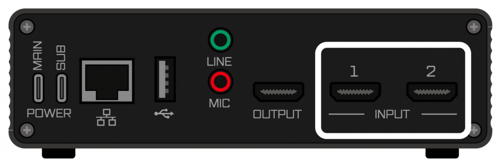
Connect HDMI signals to the HDMI 1 and HDMI 2 terminals. The HDMI video format must match the system video format (→System video format). If only one video source is to be input, input it to the HDMI 2 terminal and leave the HDMI 1 terminal unconnected.
The video being received by LiveShell W can be checked via the thumbnail display in LiveShell Studio (→Live viewing of the input video (Preview display area)).
HDMI audio input requirements
The requirements for HDMI audio signals that this product can receive are as follows. Surround audio and compressed audio cannot be received.
Linear PCM 2-channel (stereo) audio
Sampling rate of 48 kHz / 44.1 kHz / 32 kHz
Analog audio source input
There are two analog audio source input terminals: the LINE input terminal and the MIC input terminal.
Line-level stereo analog audio signals can be connected to the LINE input.
The MIC input is connected to the internal preamp and allows direct connection of a microphone.
The analog audio input is connected to the audio mixer inside the device and can be mixed with the digital audio input.
USB audio source input
By connecting a USB audio class device to the USB adapter port on this product, the input channels of the device can be input to the audio mixer on this product.
The USB audio class devices that can be used are those whose sample format can be set to 48 kHz 16 bit and that have a single input source. The behavior when a device with multiple sources is connected is undefined. In addition, connectivity with all devices is not guaranteed.
Connecting a video monitor output
The HDMI OUTPUT terminal outputs the same program video as the video stream being streamed. By connecting a display capable of receiving an HDMI signal to the HDMI OUTPUT terminal, you can monitor the program video being streamed. The output format of the HDMI OUTPUT terminal is the same as the system format (→System video format). Depending on the model of display connected, it may not be able to display video in the format output from the HDMI OUTPUT, so please check the specifications of the display you prepare thoroughly. In particular, some computer displays cannot display video such as 30p or 25p.
USB audio monitor output
By connecting a USB audio class device to the USB adapter port on this product, the output channels of the device can be used as the audio monitor output of this product. The content of the audio output as the monitor is the same as the master output.
The USB audio class devices that can be used are those whose sample format can be set to 48 kHz 16 bit and that have a single output sink. The behavior when a device with multiple sinks is connected is undefined. In addition, connectivity with all devices is not guaranteed.
Video manipulation
This product can receive two different video signals simultaneously, and outputs video obtained by applying one of the following processes to these two videos.
Select only one of the two videos
Scale down one of the two videos and composite it on top of the other
Split the screen into left and right and place the two videos side by side
Cut out video shot against a green screen and composite it on top of another video
In addition, the following effects can be added to the output video as needed.
Composite a still image on top of the video
This chapter explains how to perform these processes.
Definitions of terms related to video manipulation
Video input names
In the user interface of this product, the two video signal inputs are labeled “Input A” and “Input B”.
Input A
Input A corresponds to the video input to the HDMI INPUT 1 terminal.
Input B
Input B corresponds to the video input to the HDMI INPUT 2 terminal.
Program output
This is the final output video after switching and compositing, and is the video that is actually streamed.
Switching (video switching)
Switching is a mode in which only one of the videos, either Input A or Input B, is selected for program output. Switching can be operated with either the video select button on the main unit or LiveShell Studio.
Switching operation by the unit
Using the video select button on the main unit of this product, you can switch video by operating the unit alone. When “A” of the video select button is pressed, the program output switches to the video of Input A, and when “B” is pressed, the program output switches to the video of Input B. When switching is performed using the video select button, the video effect at the time of switching is a MIX with a transition time of 1 second.
Even when Picture-in-Picture, Split screen, or Chroma Key compositing is applied by operating LiveShell Studio, pressing the video select button on the main unit cancels the compositing and the selected input becomes the program output.
Lighting status of the video select buttons
The video select buttons indicate how the video inputs are selected by their lighting status.
When Input A is selected as the program output, video select button A lights up red, and when Input B is selected as the program output, video select button B lights up red. The other button lights up green. However, when both inputs are being used through video compositing (→Video compositing), the buttons light up as follows.
In Split screen, both video select button A and video select button B light up red.
In Picture-in-Picture or Chroma Key, the video select button for the input used as the main screen lights up red, and the video select button for the input used as the sub-screen lights up yellow.
During a switching transition by AUTO, both video select button A and video select button B flash red.
Switching operation using LiveShell Studio
To perform switching with LiveShell Studio, proceed as follows.
Select “Switching” from the slider at the top of the preview screen.
Select the desired switching destination on the preview screen (Input A or Input B). When selected, the relevant screen is displayed as “Selecting”. The following is an example of preparing to switch to Input B when Input A is being used as the program output.
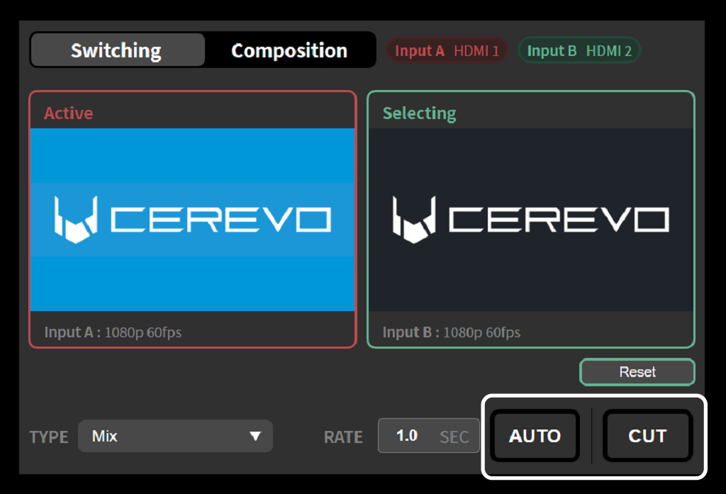
Pressing the AUTO or CUT button with the switching destination selected switches the program video output to the currently selected input. The differences between AUTO and CUT are as follows.
With AUTO, the video effect specified by TYPE is applied over the time set by RATE (→Selecting the video effect for switching).
With CUT, the video is switched instantly without applying any effect.
Selecting the video effect for switching
Video effects can be applied for smooth video switching. The effect to be applied can be selected from the TYPE pull-down menu. There are two types of video effects: Mix and Wipe.
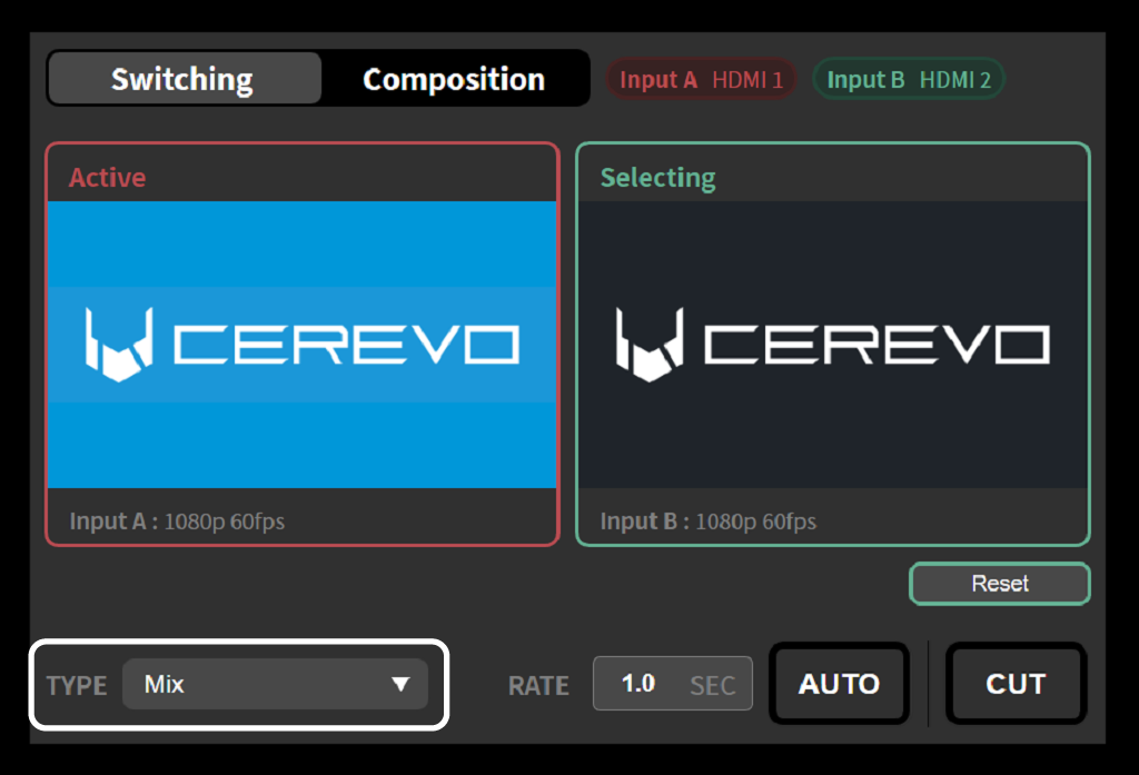
Mix
The two videos are composited by fading, transitioning smoothly between them.
Wipe
The screen is split and the dividing line is moved to transition between the two videos. Depending on the direction in which the dividing line moves, you can choose from the following four types.
Wipe (from left to right)
Wipe (from right to left)
Wipe (from top to bottom)
Wipe (from bottom to top)
Specifying the transition time of the video effect
The transition time for Mix and Wipe can be specified by entering the time in seconds in the “RATE” field. The default value is 1.0 second.
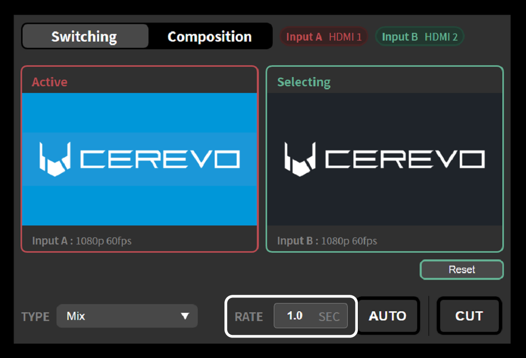
Video compositing
With this product, the two video inputs, Input A and Input B, can be composited into the program output. To use the video compositing function, first select “Composition” from the slider at the top of the preview screen, then select the compositing method to apply from “PinP”, “Split screen”, or “Chroma Key” on the left side of the preview screen.
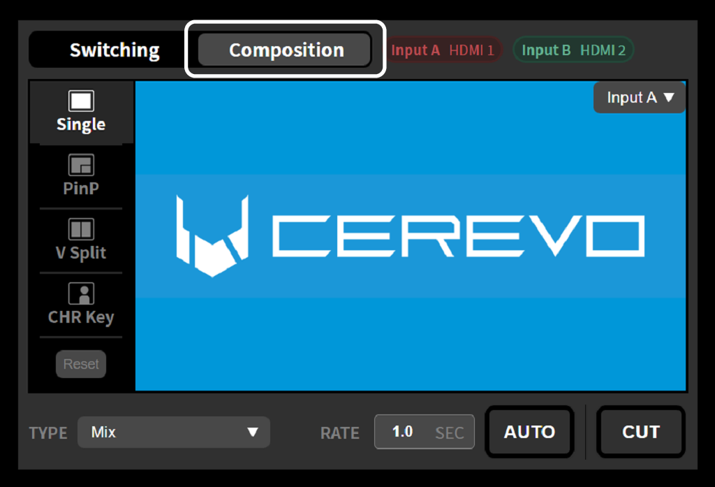
Using Picture-in-Picture (PinP)
Picture-in-Picture (PinP) is a compositing method that overlays a different, scaled-down sub-screen on top of the input that serves as the main screen. The position and size of the sub-screen can be changed freely.
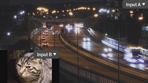
To use this compositing method, operate as follows.
Select “PinP” from the left side of the preview screen.
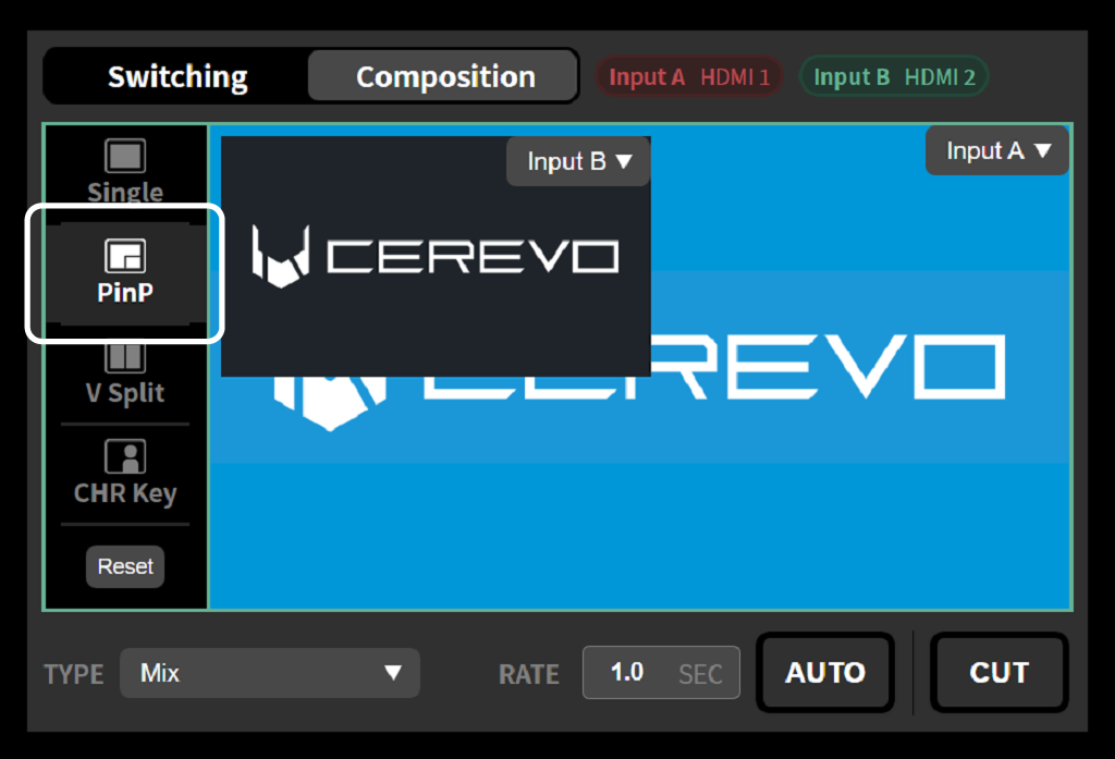
Select “Composition” from the tabs at the bottom of the preview screen.

From the “Source selection” pull-down menus under “PinP” in the Composition tab, select the input to use as the main screen and the input to use as the sub-screen. The main screen and sub-screen can also be selected from the pull-down menus displayed within the preview screen.
Use the “Size” slider under “PinP” in the Composition tab to select the size of the sub-screen. It can be adjusted as a reduction ratio relative to the full screen.
Under “Position” of “PinP” in the Composition tab, press to select the position at which to composite the sub-screen. After selecting, you can fine-tune the compositing position by operating the vertical and horizontal sliders.
Pressing the AUTO or CUT button in the preview screen switches the program video output to the composited video you have set.
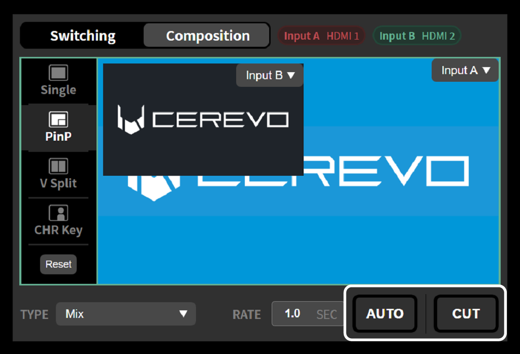
Using Split screen
Split screen is a compositing method in which a portion is cut from the two video inputs and placed side by side on the left and right. You can select one of the following ways to cut out a portion.
Center split
In Center split, the screen is divided at the center and the two videos are placed on the left and right of the dividing line. You can select one of two ways to crop the video: “Left/right crop” and “Center crop”.
Center split (Left/right crop)
In Left/right crop, the left half and right half of the original video are each cut out and used as the compositing sources.
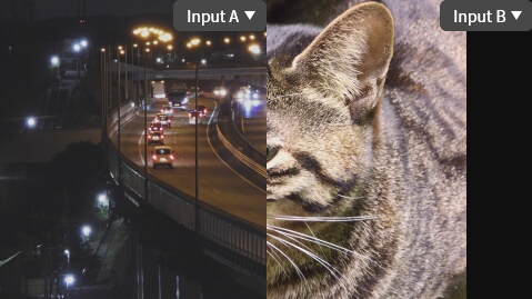
Center split (Center crop)
In Center crop, the central portion of the original video is cut out and used as the compositing source.

Seminar mode
Seminar mode is a split suited for placing the slides and the presenter’s video side by side within a 16:9 screen range. Depending on the combination of which side of the screen the slides are placed on and the aspect ratio, you can select a compositing method from the following four.
With the 4:3 options, a 4:3-sized slide and a center-cropped presenter video are composited within the 16:9 screen range. With the 16:9 options, a slightly reduced 16:9-sized slide and a center-cropped presenter video are composited within the 16:9 screen range. In each case, you can choose whether to place the slides on the right or left side of the screen.
Seminar mode (4:3 left)
A 4:3-sized slide is composited on the left and a center-cropped presenter video on the right.
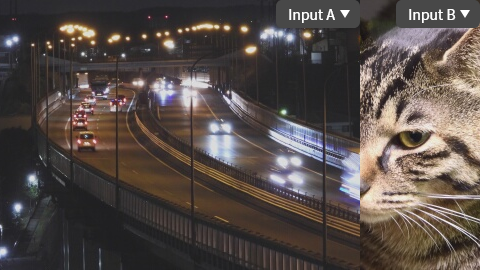
Seminar mode (4:3 right side)
Composites a 4:3-size slide on the right side and a center-cropped video of the presenter on the left side.
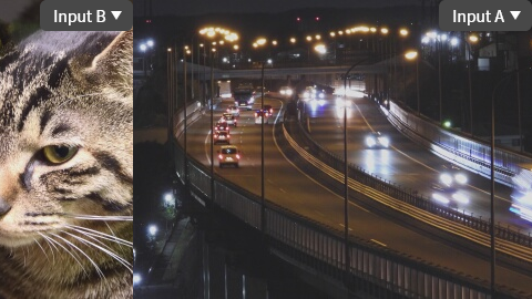
Seminar mode (16:9 left side)
Composites a slightly reduced 16:9-size slide on the left side and a center-cropped video of the presenter on the right side.
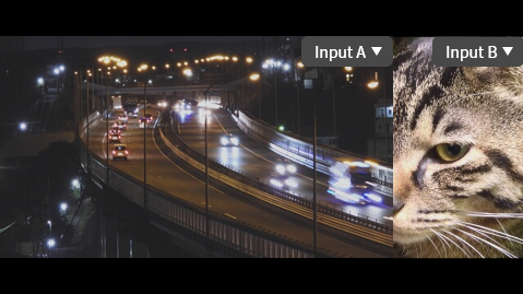
Seminar mode (16:9 right side)
Composites a slightly reduced 16:9-size slide on the right side and a center-cropped video of the presenter on the left side.
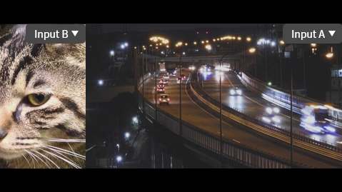
To use this compositing method, operate as follows.
Select “Split” from the left side of the preview screen.
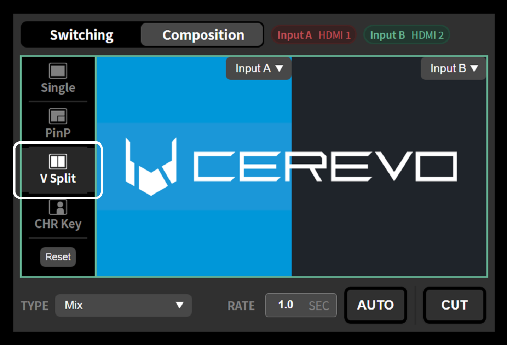
On the preview screen, select the input to use as the left half of the video and the input to use as the right half of the video.
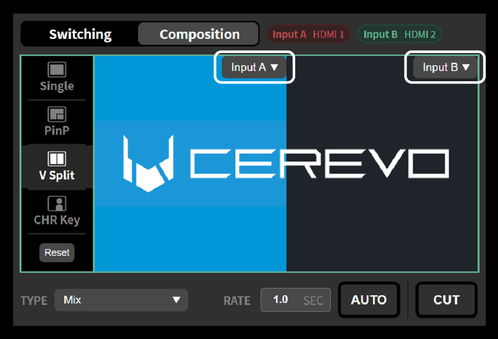
Select “Composition” from the tab at the bottom of the preview screen. Select “Split Type” from “Split” on this tab.
Pressing the AUTO or CUT button in the preview screen switches the program video output to the composited video you have set.
Using chroma key
Select “Chroma Key” from the left side of the preview screen.
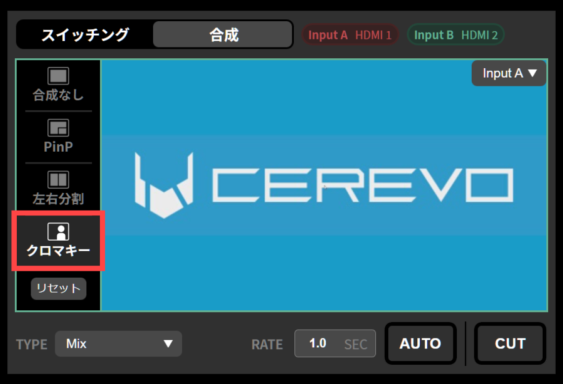
Select “Chroma Key” from the tab at the bottom of the preview screen.
From the “Source Selection” pull-down menu of “Chroma Key” in the Chroma Key tab, select the input to use as the background and the input to use as the key. You can also select the background and the key from the pull-down menus displayed in the preview screen.
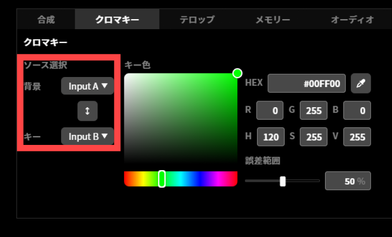
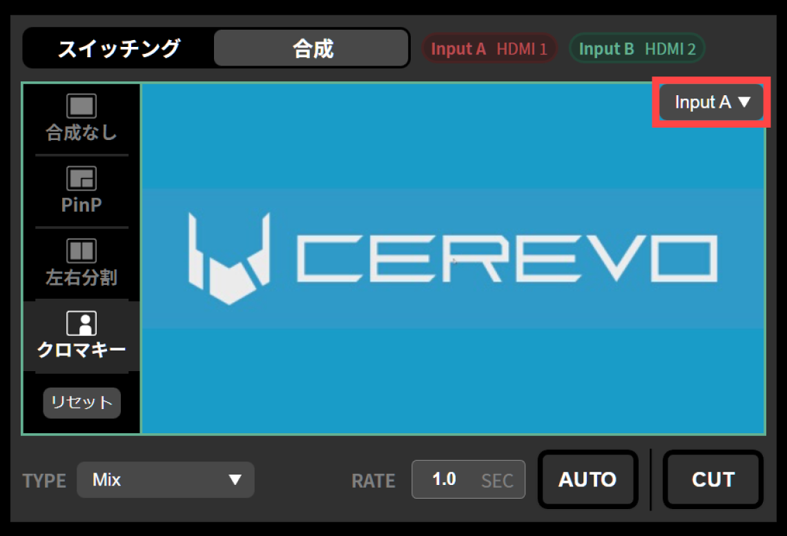
Use the color picker or the eyedropper tool to select the key color to be made transparent.
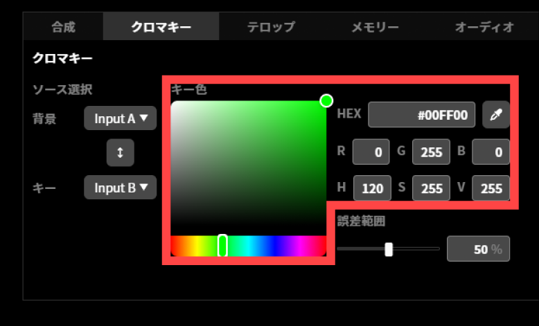
If you select the eyedropper tool, the “Key Color Selection” dialog appears. From the source selection pull-down menu at the bottom left, select the input to use as the key. After selecting the key color to be made transparent, press “OK”.
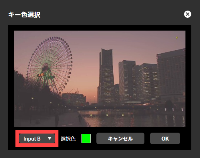
Use the “Error Range” slider or numerical input to specify the range of similar colors to be recognized as the key color.
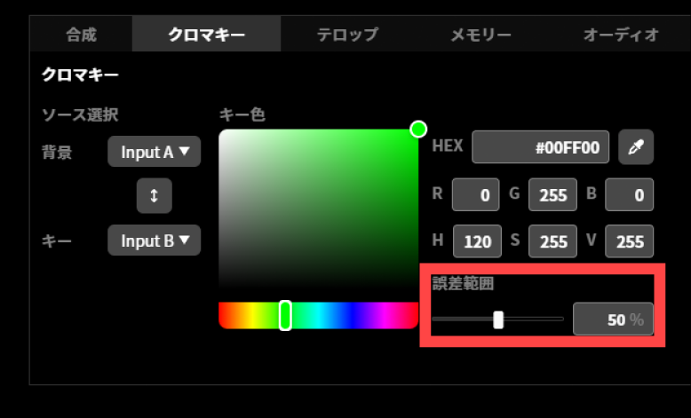
Pressing the “AUTO” or “CUT” button in the preview screen switches the program video output to the composited video you have set.
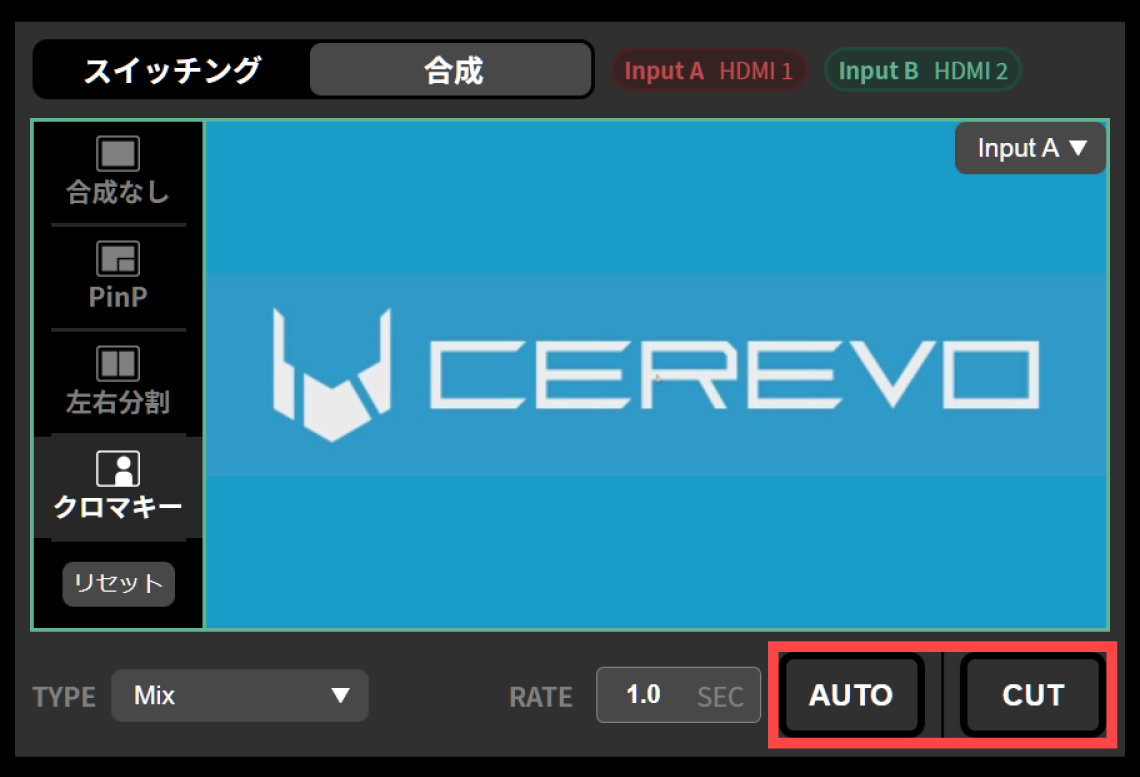
Tips for selecting the key color gamut
The chroma key function of this product can be used effectively for a color gamut where one of the three primary colors of light (red/blue/green) is predominant and the brightness is generally uniform. Composite colors (e.g., yellow) cannot be clipped well.
If the brightness of the color gamut used as the key is low, good cropping will not be possible.
To select the key color, refer to the thumbnail image and select a color that is as bright as possible within the color gamut to be used as the key color.
Keep the error range at roughly 50% or less. If it exceeds 50%, unintended colors may also be recognized as the key.
The chroma key composition result is not displayed on the preview screen. Adjust it while viewing the HDMI OUT program output or the streaming video.
Video effects when compositing video
When compositing video, transition video effects can be applied only to the following combinations. No video effect is applied when switching between different composition modes.
Transition between no composite and PinP
The Mix effect can be applied only when transitioning between the same input and the input used as the main screen for PinP. All other effects will be disabled even if selected.
Transition between no composite and split
Only Wipe can be used to transition between no composite and split. Also, regardless of the wipe direction specified, the wipe will be in the direction that is actually applicable according to the input to which it is being switched.
Transition between no composite and chroma key
The Mix effect can be applied only when transitioning between the same input and the input used as the background for chroma key. All other effects will be disabled even if selected.
Using telops
The telop feature lets you composite any still image and text onto the program output video. You can use it to display a message to viewers or to show a logo on the program output. The telop feature described in this chapter is available with firmware revision v1.5.0 or later.
Basics of creating a telop
A telop on this product consists of multiple “layers”, and is expressed as the composite of these stacked layers. There are three types of layers: “image layers”, “text layers” and “clock layers”. You can create the telop you want by first creating an empty telop and then adding the raster images and text strings needed as its content as image layers, text layers and clock layers respectively.
When using an image layer, you must create the still image to be used as the layer in advance with image editing software or the like, and upload the image to this product’s memory on LiveShell Studio. Text layers and clock layers can be entered and edited on LiveShell Studio.
Creating a new caption
To create a new caption, follow these steps.
To create a telop that consists of a single image layer only, you can also create a new telop by dragging and dropping a PNG image file that meets the conditions for an image layer onto the telop list. When you do this, the file name of the uploaded image file is used as the telop name.
First, select the “Caption” tab and click the “New” button. If you have already saved telops, a list of their thumbnails is displayed in this area.

Clicking the “New” button at the bottom opens the telop editing screen. At this point the telop has no layers making up its content and is uniformly transparent.
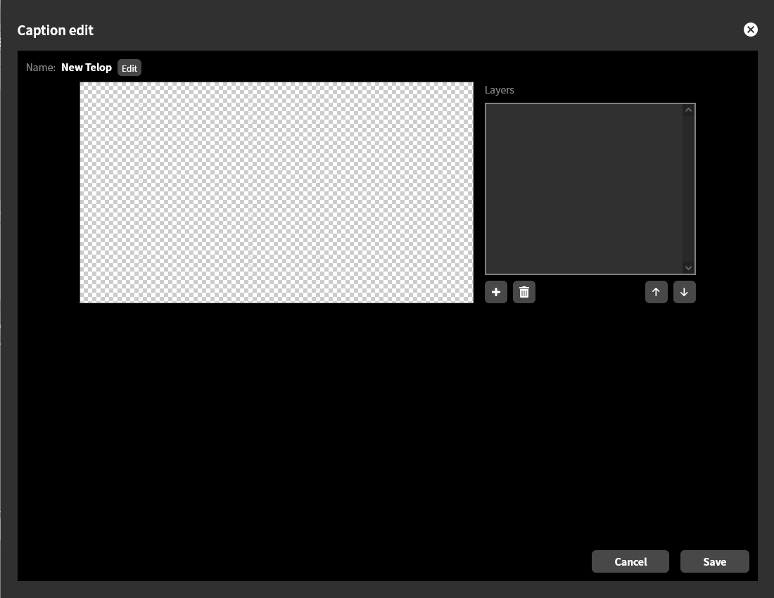
You can give a telop any name you like. The name of a newly created telop is “New Telop”. You can change the name by clicking the “Edit” button next to it.
Adding a Layer
To add a new layer to a telop, click the “+” button at the bottom of the layer list on the telop editing screen. A submenu appears for choosing “Image” or “Text”; select “Image” to add an image layer, or “Text” to add a text layer.
Adding an image layer
When you select “Image” in “Adding a layer”, you are prompted to upload an image file. Select the image file you prepared in advance on your operating computer or the like and upload it. This image must meet the following conditions.
The file format must be a PNG image.
Interlaced PNG is also supported (v1.5.0 or later).
It is preferable that the image resolution be the same as the system video format (→System video format).
For example, if the system video format is set to 1920x1080 60p, it is recommended an image size of 1920x1080 dots.If the system video format is set to 1280x720 60p, we recommend an image size of 1280x720.
If the image resolution differs from the system resolution, it will be adjusted to the same size as the system resolution, ignoring the aspect ratio, and then composited.
The file size must be 4 MB or less.
The example below shows the state immediately after uploading an image layer depicting a logo.
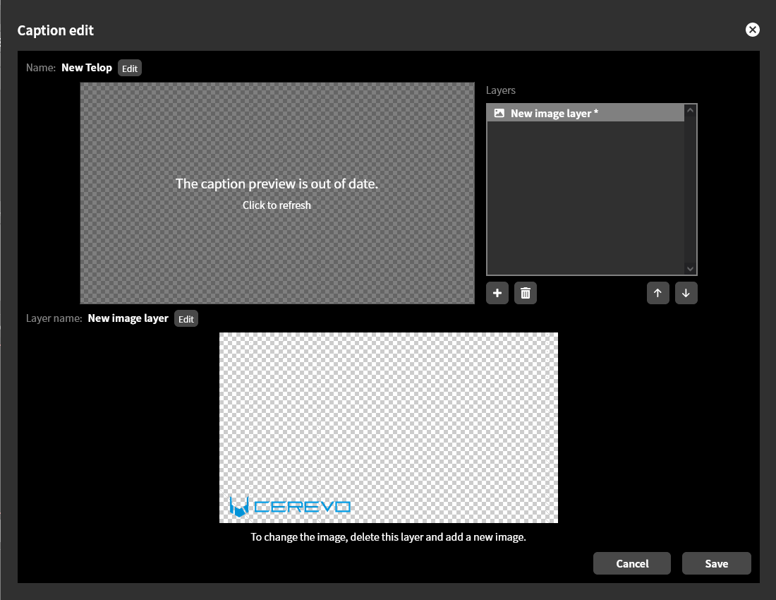
Adding a text layer
When you select “Text” in “Adding a layer”, the text telop editing screen is displayed. On this screen, in addition to the text content to be displayed as a telop, you can edit instructions such as the size, color and on-screen placement of the text.
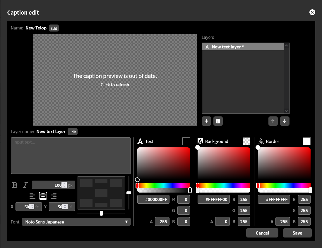
To check how the edited text and its composite with other layers will look, click the preview screen. The example below shows the result of compositing the text string “Live!” in addition to the image layer for the logo, displayed as a preview.
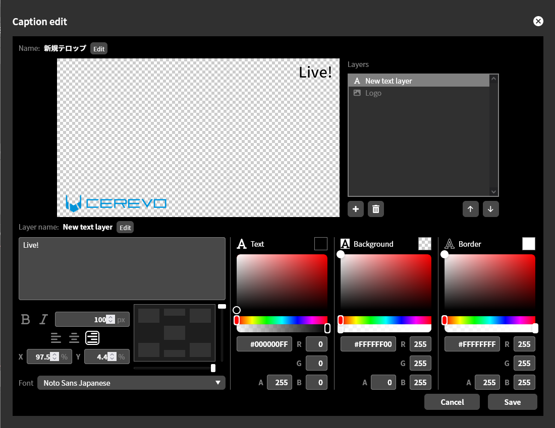
Note that the preview is not updated automatically.
Text editing
Enter the characters to display as a telop in the text box labeled “Input text…”.
Text font and size
You can select the text font from the “Font” pull-down. The text size can be specified in pixels. The default size is 100 px. Also, to make the text bold, click “B”; to make it italic, click “I”.
Text alignment, horizontal
You can select the horizontal alignment of the text from “Left,” “Center,” or “Right.” This selection determines which part of the text will be used as the basis for positioning when you “Specify text position” as explained in the next section. The criteria for positioning are as follows:
Left edge of text if left-justified
Center of text if centered
Right edge of text if right-justified
The horizontal alignment of the text can be set manually, and it is also set automatically when you position the text using the “position box”.
Text positioning
You can position the text within the text area using the positioning box, fader, or by entering the X and Y coordinates directly.
Using the position box, you can place the text in one click at one of “Center”, “Top center”, “Bottom center”, “Top left”, “Bottom left”, “Top right” or “Bottom right” within the telop area. The horizontal alignment of the text is also set automatically according to this placement. When placed at “Center”, “Top center” or “Bottom center”, the horizontal alignment is set to “Center” and the text is centered within the telop area. When placed at “Bottom left” or “Top left”, the horizontal alignment is set to “Left” and the left edge of the text is aligned to the left edge of the telop area. Similarly, when placed at “Bottom right” or “Top right”, the horizontal alignment is set to “Right” and the right edge of the text is aligned to the right edge of the telop area.
You can fine-tune the text position horizontally by moving the slider below the position box, and vertically by moving the slider to the right of the position box. You can also specify the position by entering immediate values for the X and Y coordinates. The unit of the values is percent, given as a ratio to the horizontal and vertical resolution with the upper-left of the screen as the origin.
Text color and transparency
You can specify the color of the text body, background, and border separately. You can also specify the transparency of each element. Areas without any of these elements will be transparent.
The color can be specified by selection with the color picker, by specifying it in #RRGGBBAA hexadecimal format, or by entering immediate values for red, green, blue and transparency. When entering colors as immediate values, 0 is the minimum and 255 is the maximum. For transparency, 0 is fully transparent and 255 is fully opaque. Due to rounding, the transparency value may deviate from the set value by 1, but this is not abnormal.
Adding a clock layer
To add a clock layer, follow the steps below.
When you select “Clock” in “Adding a layer” described in the previous section, the clock telop editing screen is displayed.
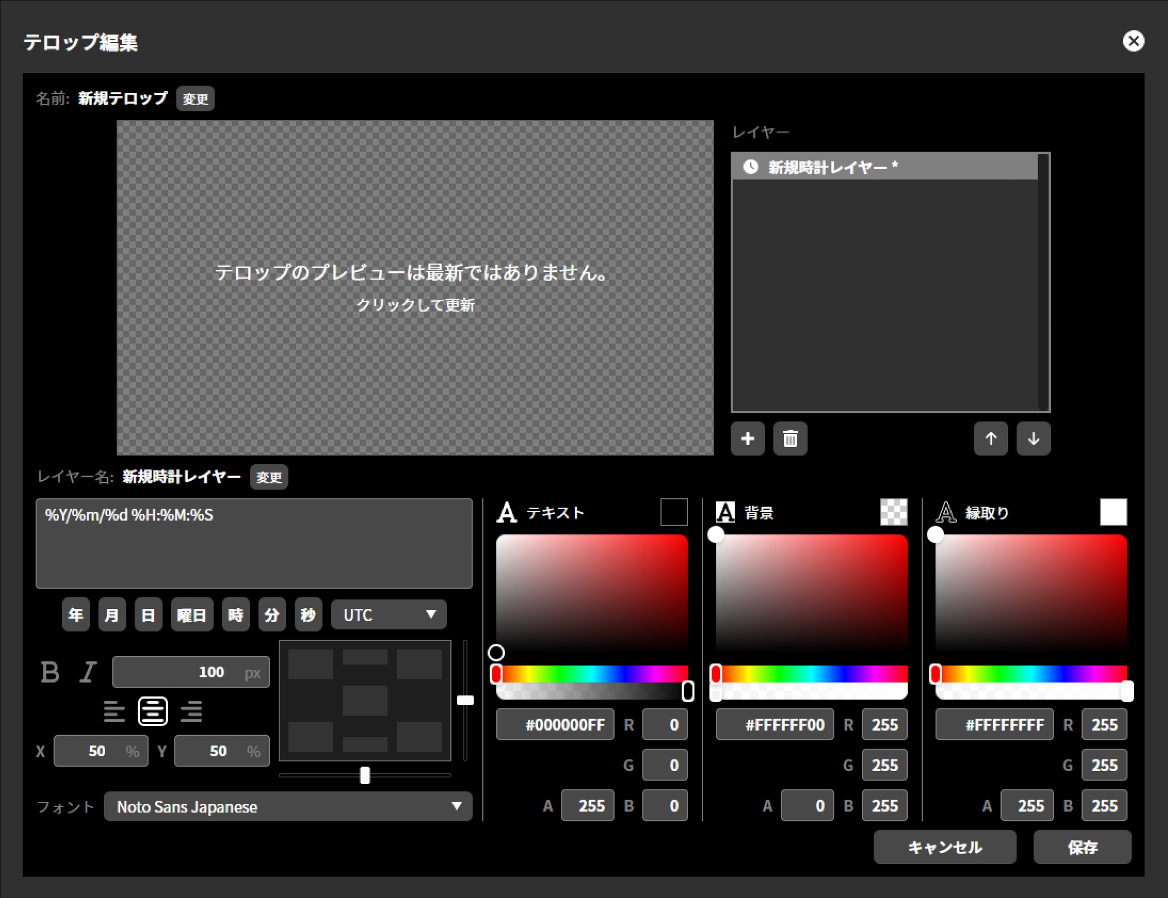 On this screen, in addition to the content to be displayed as the clock, you can edit instructions such as the size, color and on-screen placement of the text.
The text editing method is the same as for the text layer. The editing method differs depending on each item. Refer to the individual procedures below for each.
The preview is not updated automatically. To check it, click “Preview” to refresh.
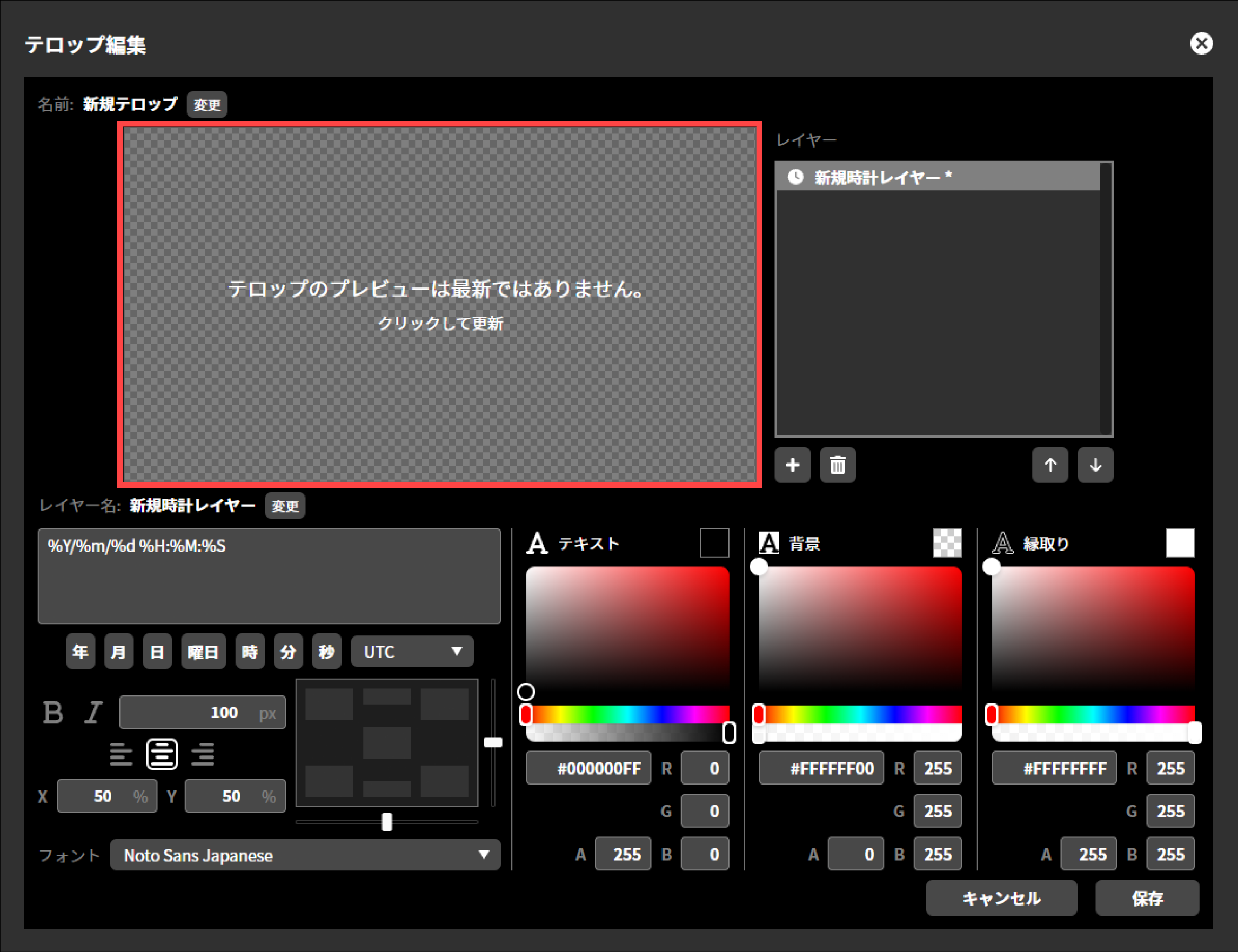
To edit the layer name, press “Edit”.
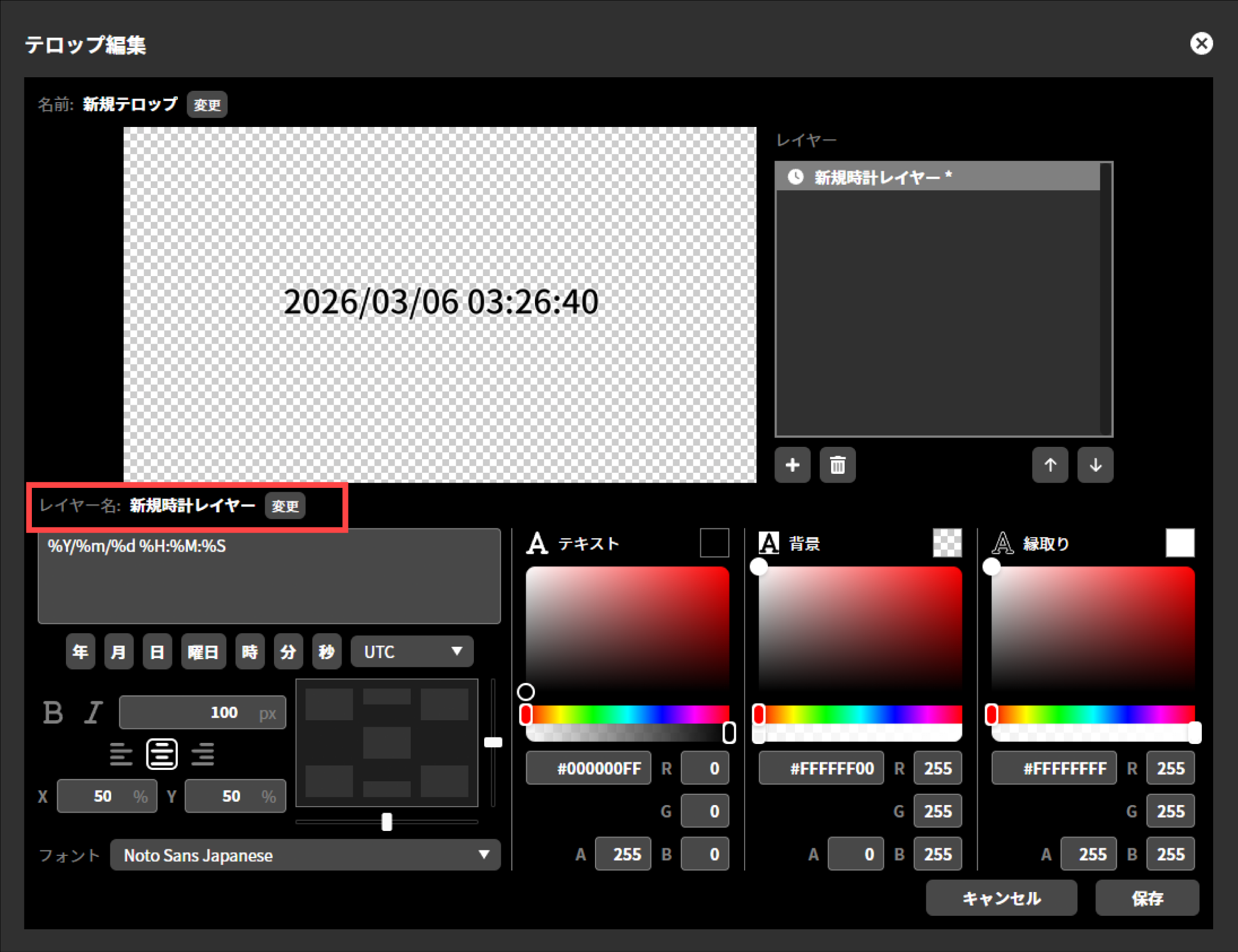
Enter any layer name and press “Save”.
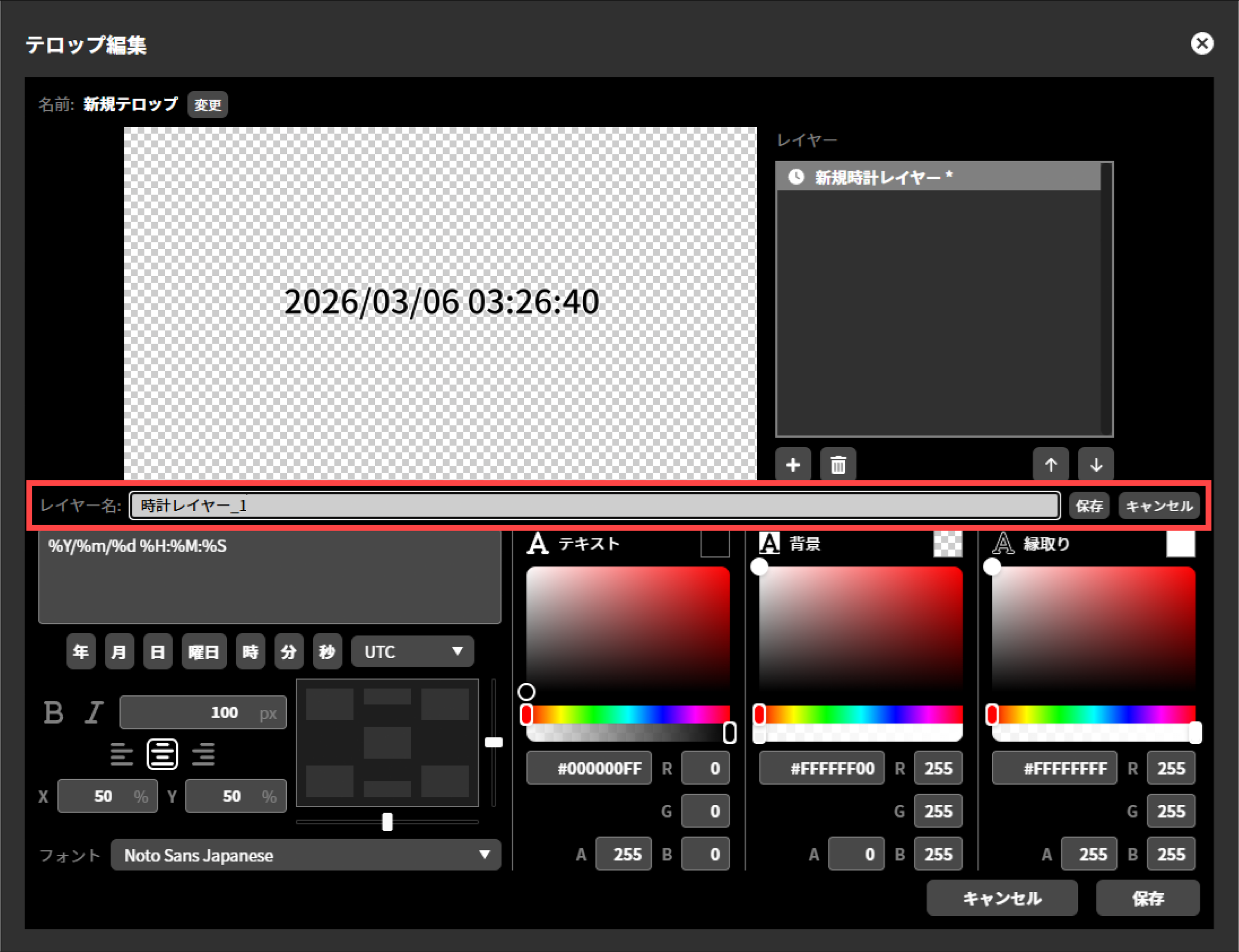
When all editing is complete, click “Save”.
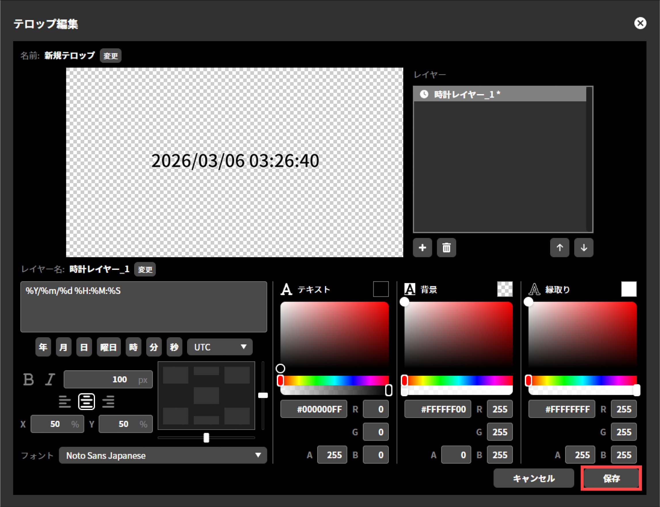
Once saving is complete, the “Edit Caption” dialog will close automatically.
Clock display format
You can also insert specifiers using the buttons below the text box. In addition, you can select the time zone from the pull-down menu to its right. The default is the time zone set in the unit settings (→Time zone setting).
Specifier |
Meaning |
Display example |
|---|---|---|
%Y |
Year (4 digits) |
2025 |
%y |
Year (2 digits) |
25 |
%g |
Japanese era name |
令和 |
%G |
Japanese era year |
7 |
%m |
Month (number) |
10 |
%b |
Month (English abbreviation) |
Oct |
%B |
Month (English full name) |
October |
%d |
Day |
05 |
%j |
Day of the year |
278 |
%a |
Day of week (English abbreviation) |
Sun |
%A |
Day of week (English full name) |
Sunday |
%v |
Day of week (Japanese abbreviation) |
Day |
%V |
Day of week (Japanese full name) |
日曜日 |
%H |
Hour (24-hour) |
14 |
%I |
Hour (12-hour) |
2 |
%p |
AM/PM |
PM |
%q |
Japanese AM/PM |
午後 |
%M |
Minute |
05 |
%S |
Second |
30 |
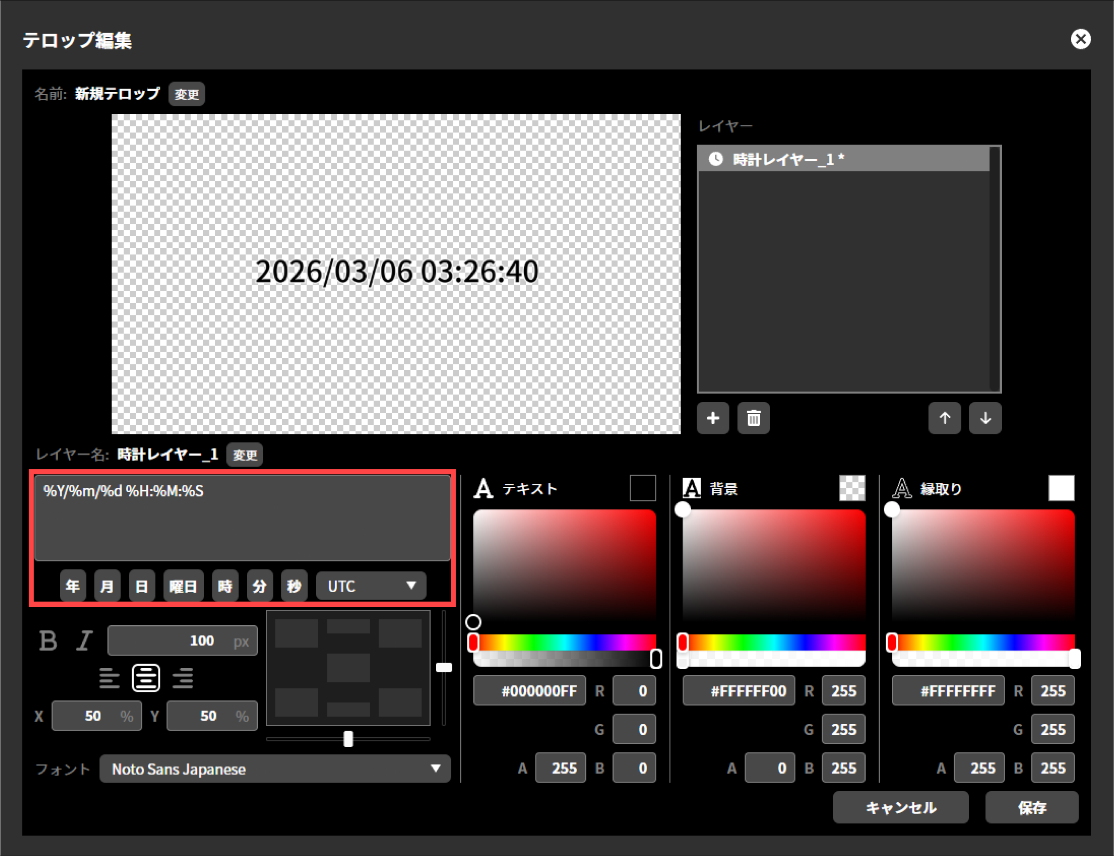
Editing layer
In the layer list, select the layer you want to edit to re-edit that layer. The following items can be re-edited.
Naming layer
You can give image layers and text layers any name you like. You can change the name by clicking the “Change” button next to the layer name.
Re-editing text layer
You can edit text layers in the same way as when you added a layer.
Re-editing image layer
An image layer cannot be edited. To change the contents of an image layer, first delete the layer and then add a new image layer.
Changing the layer order
In the layer list, select the layer whose stacking order you want to change and click “↑” or “↓” to change its stacking order. Layers that are higher up are composited in front.
Deleting a layer
In the layer list, select the layer you want to delete and click the trash icon to delete the selected layer. A deleted layer cannot be restored.
Saving the caption
After adding and editing layers, click the “Save” button to save the telop and finish editing. Note that clicking “Cancel” finishes editing without saving the changes.
Re-editing caption
You can re-edit a telop by clicking the “Edit” icon next to the telop thumbnail. In re-editing, you can change the layer order, replace layers, re-edit text layers and so on.
Deleting caption
You can delete a telop by clicking the “trash” icon next to the telop thumbnail. Once a telop is deleted, it cannot be restored.
Duplicating caption text
By selecting a telop thumbnail and clicking the “Duplicate” button, you can create a new telop that duplicates all layers of that telop. The duplicated telop can be re-edited, and this editing does not affect the original telop.
How to composite a telop
The procedure to composite a created telop onto the program output is as follows.
Click the thumbnail of the telop image you want to apply to make it selected.
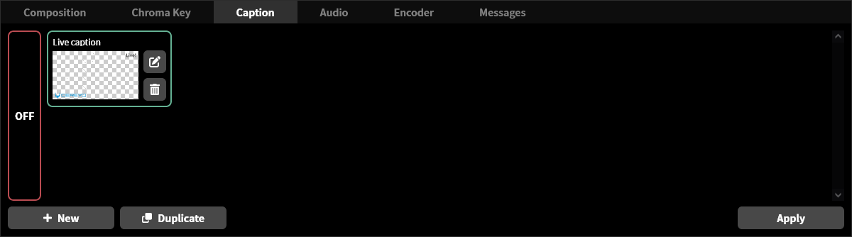
Click the “Apply” button in the lower right.
If you select and apply another image while a telop is already being composited, the composited telop switches to the newly selected image. The procedure to stop compositing a telop image is as follows.
Click “OFF” on the left side of the telop thumbnail.
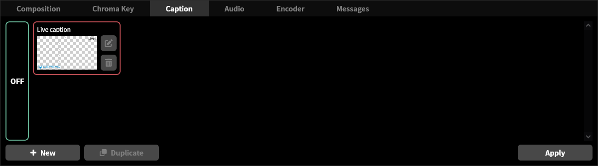
Click the “Apply” button in the lower right.
Video encoder settings
The program output of this product is internally connected to an H.264 encoder, which compresses and converts video into a code suitable for network distribution. The following settings can be adjusted for the video encoder.
Video bitrate setting
Unit menu / MAIN MENU →Encoder →Video Bitrate
LiveShell Studio / Main screen →Encoder →Bitrate
Factory default / 8192 kbps
This is the setting for the average bitrate output by the H.264 encoder. Use an appropriate setting according to the recommended settings of the streaming platform and network bandwidth.
Video frame rate setting
Unit menu / MAIN MENU →Encoder →Frame Rate
LiveShell Studio / Main screen →Encoder →Frame rate
Factory default / Full
This is the setting for the number of frames per second output by the H.264 encoder. Use an appropriate setting according to the recommended settings of the streaming platform and network bandwidth. The following settings can be made for this product.
When the system video format is set to 60p or 50p
When set to “Full”, the output frame rate is the same as the system video format (60 fps or 50 fps).
When set to “Half”, the output frame rate is half the frame rate of the system video format (30 fps or 25 fps).
When the system video format is set to something other than 60p or 50p
Only the “Full” setting is available. The output frame rate is the same as the system video format.
Keyframe interval setting
Unit menu / MAIN MENU →Encoder →KeyFrameInterval
LiveShell Studio / Main screen →Encoder →Key frame interval
Factory default / 120
This setting determines how many frames apart keyframes (I-pictures) are inserted into the H.264 encoder output. Set it appropriately according to the recommended settings of the streaming target and the network bandwidth. Normally, set it so that a keyframe is sent once every 2 seconds (twice the frame rate value).
H.264 profile setting
Unit menu / MAIN MENU →Encoder →H.264 Profile
LiveShell Studio / Main screen →Encoder →H.264 profile
Factory default / High
This is the encoding profile setting used by the H.264 encoder. You can select from Baseline, Main, or High. Normally, set it to High.
Audio operation
This product is equipped with an audio mixer. It can mix the digital audio signals from the two HDMI inputs, the analog audio from the MIC and LINE inputs, and the audio input from a USB audio device, as well as the audio played back by the BGM player built into this product. This chapter describes how to operate the audio mixer and the BGM player.
How to operate the audio mixer
Unit menu / MAIN MENU →Audio →Mixer
LiveShell Studio / Main screen →Audio tab →Audio mixer
The audio mixer can be operated using both LiveShell Studio and the main unit’s control dial.
The LiveShell Studio audio mixer
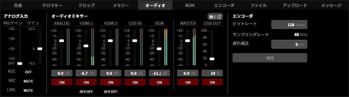
Selecting “Open” shown in the LiveShell Studio audio mixer allows you to perform more detailed operations.
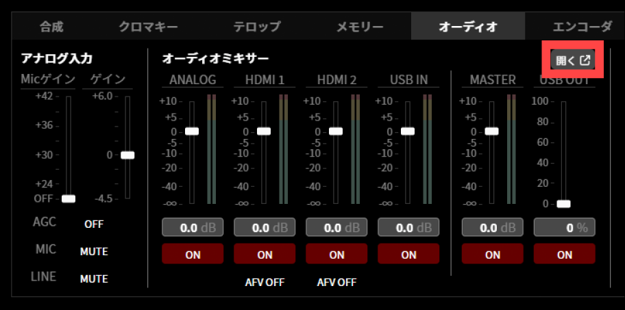
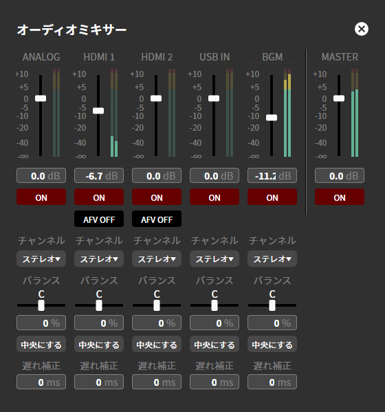
The audio mixer that can be operated with the main unit’s control dial
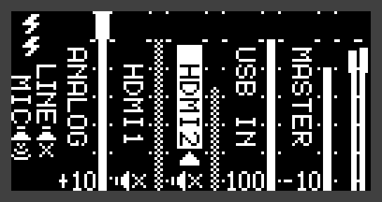
Analog audio input gain adjustment
Unit menu / MAIN MENU →Audio →Analog Gain
LiveShell Studio / Main screen →Audio tab →Analog input
Factory default / 0 dB
This is the gain adjustment value of the variable gain amplifier for the analog audio inputs (MIC input and LINE input).
The configurable range is as follows.
-4.5 dB to +6 dB
MIC input preamp gain adjustment
Unit menu / MAIN MENU →Audio →Analog Mic Gain
LiveShell Studio / Main screen →Audio tab →Analog input
Factory default / OFF
This is the preamp gain adjustment value for the MIC input.
The configurable range is OFF and, in 3 dB steps, as follows.
+24 dB to +42 dB
Analog audio input mute
Unit menu / MAIN MENU →Audio →Mixer
LiveShell Studio / Main screen →Audio tab →Analog input
Factory default / MUTE (muted)
These are the individual mute settings for the MIC input and LINE input among the analog audio inputs. In LiveShell Studio, clicking the “ON” or “MUTE” button toggles the state. It is unmuted when the button shows “ON” and muted when it shows “MUTE”.
When you unmute the MIC input or LINE input, the audio level meter floor may rise even when there is no input, due to the noise floor of the input circuitry and amplifier. We recommend muting these inputs when you are not using them. The factory default setting is mute.
AGC (automatic gain control) for analog audio input
Unit menu / MAIN MENU →Audio →Analog AGC
LiveShell Studio / Main screen →Audio tab →Analog input
Factory default / AGC OFF
This setting determines whether AGC (automatic gain control) is applied to the analog audio input. When AGC is enabled, in addition to automatically correcting the gain according to the input volume level, a denoiser that reduces noise mixed into the input audio (especially hiss) is enabled.
AGC is effective when a microphone is connected to record human speech. When applied to sound other than speech, such as music, problems such as oscillation or distortion may occur. Oscillation may also occur if the input level is too high. In that case, lower the analog audio gain.
Level adjustment for each source
Unit menu / MAIN MENU →Audio →Mixer
LiveShell Studio / Main screen →Audio tab →Audio mixer
Factory default / 0 dB
The attenuation can be adjusted for each source: Analog, HDMI1, HDMI2, USB IN, and BGM. In LiveShell Studio, you can adjust it using the slider with the mouse or by entering a value directly.
Analog applies the adjustment to the mixed signal of the MIC input and LINE input.
The configurable range is as follows.
0.0 dB (no attenuation) to -∞ (full attenuation)
Mute for each source
Unit menu / MAIN MENU →Audio →Mixer
LiveShell Studio / Main screen →Audio tab →Audio mixer
Factory default / ON (unmuted)
You can set input mute for each source: Analog, HDMI1, HDMI2, USB IN, and BGM. In LiveShell Studio, clicking the “ON” or “MUTE” button toggles the state. It is unmuted when the button shows “ON” and muted when it shows “MUTE”.
Analog mutes the mixed signal of the MIC input and LINE input. The MIC input and LINE input can be muted individually (→Analog audio input mute).
Channel setting for each source
Unit menu / Not configurable
LiveShell Studio / Main screen →Audio tab →Audio mixer →Open
Factory default / Stereo
You can set the channel of the input audio signal for each source: Analog, HDMI1, HDMI2, USB IN, and BGM. When setting it to monaural audio, select “Left only”, “Right only”, or “L+R Mix” according to the input audio signal.
The configurable channels are as follows.
Stereo
Left only
Right only
L+R Mix
Balance (PAN) setting for each source
Unit menu / Not configurable
LiveShell Studio / Main screen →Audio tab →Audio mixer →Open
Factory default / 0 % (C)
You can set the balance (localization) of the input signal for each source: Analog, HDMI1, HDMI2, USB IN, and BGM. You can adjust it using the slider with the mouse or by entering a value directly. Pressing “Center” positions the sound image at the center.
The configurable range is as follows.
-100 % (L) to 100 % (R)
Delay correction setting for each source
Unit menu / MAIN MENU →Audio →Source Delay
LiveShell Studio / Main screen →Audio tab →Audio mixer →Open
Factory default / 0 ms
You can set the correction amount in milliseconds for each source: Analog, HDMI1, HDMI2, USB IN, and BGM. The video leads relative to the standard timing by the amount of the set value.
The configurable range is as follows.
0 to 300 ms
AFV for HDMI audio
Unit menu / MAIN MENU →Audio →AFV
LiveShell Studio / Main screen →Audio tab →Audio mixer
Factory default / OFF (no AFV)
AFV (Audio Follow Video) is a function that controls audio muting in conjunction with HDMI video switching. When AFV is set to ON, the audio of the HDMI input selected by switching is unmuted, and the audio of the unselected HDMI input is muted. AFV has no effect when compositing other than switching (such as PinP) is being performed. If a video transition time is set, the audio crossfades over the same time.
Master volume control and mute
Unit menu / MAIN MENU →Audio →Mixer
LiveShell Studio / Main screen →Audio tab →Audio mixer
Factory default / 0 dB | ON (unmuted)
Use Master to adjust the level of the output audio after mixing. The operation method is the same as the level adjustment for each source. When Master is muted, the output becomes completely silent.
USB audio monitor output volume control and mute
Unit menu / MAIN MENU →Audio →Mixer
LiveShell Studio / Main screen →Audio tab →Audio mixer
Factory default / 0 % | ON (unmuted)
This is the monitor audio level setting for output to USB audio. This setting is applied to the mixer of the relevant channel when a USB audio device with an output channel is connected. The adjustment resolution and the volume level after adjustment depend on the specifications of the device’s mixer. Also, some devices do not support volume adjustment or mute.
BGM player
This product is equipped with a BGM player function that plays back music files saved on an SD memory card or USB memory device. The played-back audio is input to the audio mixer as the “BGM” source, so it can be mixed together with other audio inputs and included in the audio of the stream or recording.
Placing music files
To play music files with the BGM player, create a directory named “bgm” at the top level of the SD memory card or USB memory device and save the files in it. If you provide a “bgm” directory on both the SD memory card and the USB memory device, the files from both are merged into a single playlist.
The supported audio file formats are as follows.
.mp3
.m4a
.aac
.wav
.flac
.ogg
Playback operation
LiveShell Studio / Main screen →BGM tab
The BGM player is operated from the BGM tab in LiveShell Studio. The BGM tab displays the file name of the currently playing track, its position in the playlist (current track number / total number of tracks), and the following operation buttons.
Play / Pause: Each press toggles between the playing and paused states.
Stop: Stops playback and returns to the beginning of the track.
Next track / Previous track: Moves to the next or previous track in the playlist. When operated at the beginning or end of the playlist, it wraps around to the last or first track, respectively.
Switch loop mode: Described later.
The BGM tab during playback
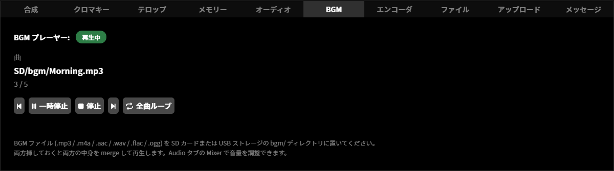
The BGM tab while stopped
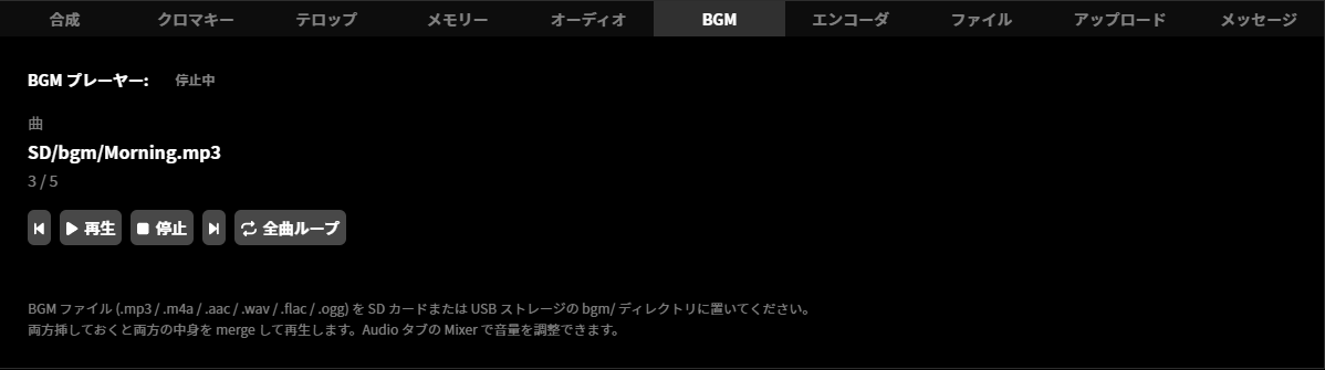
Switching loop mode
The BGM player has the following two loop modes. Each press of the loop mode toggle button on the BGM tab switches between them.
Loop all tracks: Plays all tracks in the playlist in order, and when the end is reached, returns to the first track. This mode is the factory default setting.
Loop current track: Repeatedly plays only the currently playing track.
The state with Loop current track selected (the loop mode toggle button is highlighted in blue)
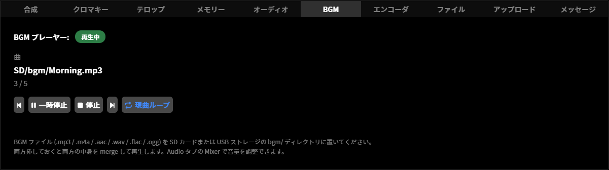
Input to the mixer
The audio played back by the BGM player is treated as the “BGM” source of the audio mixer. Just like other sources, you can perform operations such as level adjustment, mute, channel setting, balance (PAN), and delay correction. For details, refer to How to operate the audio mixer.
Behavior when inserting or removing an SD memory card or USB memory device
If you remove the medium on which the currently playing track is stored during playback, the playlist is automatically rescanned. If tracks remain on the other medium, playback switches to the next track from there; if no tracks remain on either medium, playback stops. If you insert or remove the medium that does not contain the currently playing track, playback continues.
Insertion or removal while stopped or paused is not automatically reflected in the playlist. To reflect the result of insertion or removal in the playlist, perform a playback operation. This also applies when you reinsert a medium you removed.
Behavior when no music files are found
If there are no audio files in the “bgm” directory on either the SD memory card or the USB memory device, playback will not start even if you perform a playback operation, because the playlist is empty, and a message indicating this is displayed on the BGM tab. Check that the audio files are correctly placed on the SD memory card or USB memory device.
The BGM tab when no music files are found
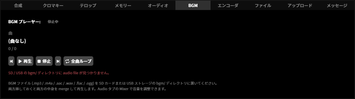
Audio encoder
The output of the audio mixer is internally connected to an AAC-LC encoder. The AAC-LC encoder compresses the PCM audio signal and converts it into a code suitable for network streaming. The following settings can be adjusted for the audio encoder.
Audio bitrate setting
Unit menu / MAIN MENU →Encoder →Audio Bitrate
LiveShell Studio / Main screen →Audio tab →Bitrate
Factory default / 128 kbps
This is the audio bitrate setting output by the AAC-LC encoder. Set it to a rate appropriate for the streaming target. The sampling rate is fixed at 48 kHz and cannot be set.
The configurable range is as follows.
48 to 256 kbps
Output audio delay correction setting
Unit menu / MAIN MENU →Encoder →Audio Delay
LiveShell Studio / Main screen →Audio tab →Delay compensation
Factory default / 0 ms
This value corrects the discrepancy between video and audio, and the correction amount can be set in milliseconds. Setting a negative value makes the audio lead relative to the standard timing, and setting a positive value makes the video lead relative to the standard timing.
The configurable range is as follows.
-300 to 300 ms
Streaming target settings
On this product, by configuring streaming targets, you can transmit the encoded video and audio to an IP network and record them on storage media. Streaming target settings can be configured in LiveShell Studio. They cannot be configured using the main unit.
Overview of streaming target settings
A streaming target is the destination to which the video and audio stream generated by this product’s encoder is sent, and can be broadly divided into two types: network streaming and recording.
This product can send the same stream to up to three streaming targets simultaneously. Therefore, you can have up to three streaming target settings enabled at any one time. On the other hand, there is no limit to the total number of streaming target settings that can be saved on this product. For example, if there are seven streaming target settings saved on this product as shown in the figure below, you can enable any three of the seven as the streaming targets actually used. An enabled streaming target is specifically called a “channel”.
         Streaming Targets                   Targets selected as Channels
    ~~~~~~~~~~~~~~~~~~~~~~~~~~~~             ~~~~~~~~~~~~~~~~~~~~~~~~~~~~
    Stream Target 1) ExampleTube  ----------------> [ Channel 1 ]
    Stream Target 2) RTSP Server        +---------> [ Channel 2 ]
    Stream Target 3) LiveExample        |   +-----> [ Channel 3 ]
    Stream Target 4) Recording    ------+   |
    Stream Target 5) 5555-Video             |
    Stream Target 6) UDP                    |
    Stream Target 7) test-live  ------------+
Protocols available for network streaming
The application protocols that can be used for network streaming are as follows.
RTMP and RTMPS
These are protocols used to send video and audio to major live streaming platforms. Whereas RTMP sends the stream in plain text, RTMPS encrypts it using Transport Layer Security. Some platforms specify the use of RTMPS.
In general, to stream via RTMP or RTMPS, you must issue an account on the live streaming platform and obtain an RTMP URL and a stream key. In addition, the recommended settings for the encoder and other components vary depending on the destination platform, so check these as well before configuring this device.
RTSP Server Mode
RTSP allows this product to act as a server and distribute video and audio to connected clients.It is a protocol suitable for use on local networks, such as for viewing program output confirmation or for distribution within a facility.
MPEG2-TS over UDP
MPEG2-TS over UDP is a mode in which video and audio multiplexed as an MPEG2 Transport Stream are sent without any procedures as a UDP datagram payload. This protocol is suitable for transmitting video to video decoders that can receive this protocol.
Recording live streaming
You can also set “Recording” as one of the targets. In this case, the stream is recorded to the storage media attached to this product in MP4 container or MPEG2-TS format. The media that can be used as the recording target are as follows:
Note that if you select MP4 as the recording container, recorded data may be corrupted if the product loses power during recording or if the recording termination process is not completed properly.
SD card
The recording target is the SD card inserted into the SD card slot on the main unit. The SD cards that can be used are limited to SD, SDHC, and SDXC cards formatted in FAT32 or exFAT format.
USB flash drive
The recording target is the USB drive connected to the USB port on the main unit. The USB drives that can be used are limited to mass storage devices formatted in FAT32 or exFAT format.
Basic operation of target settings
To add a target, follow the steps below.
Click the gear icon at the top of the program output screen.
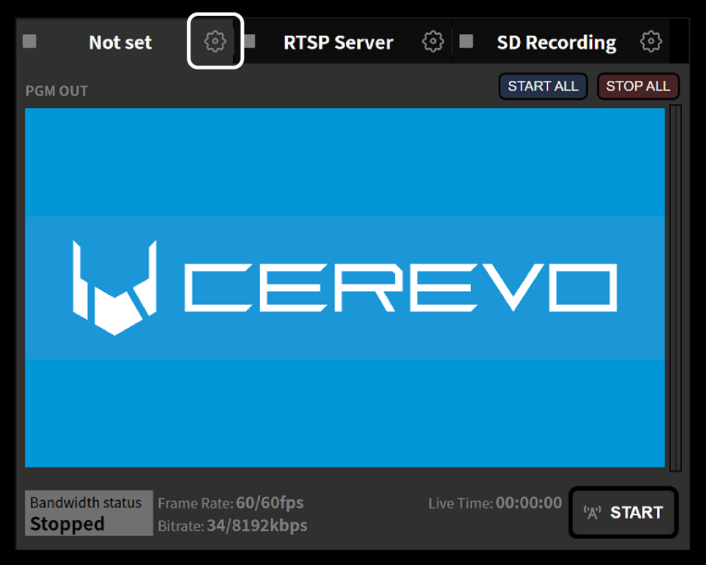
In the factory default state, as setting examples, “RTSP Server” is pre-configured on Channel 2 and “SD Recording” is pre-configured on Channel 3. Channel 1 is unconfigured. This procedure is described on the assumption that a new setting is applied to Channel 1, but it is acceptable to rewrite Channel 2 or Channel 3.
On the settings screen that appears, click the “Change” button for the channel to which you want to apply the settings. In this example, Channel 1 is selected.
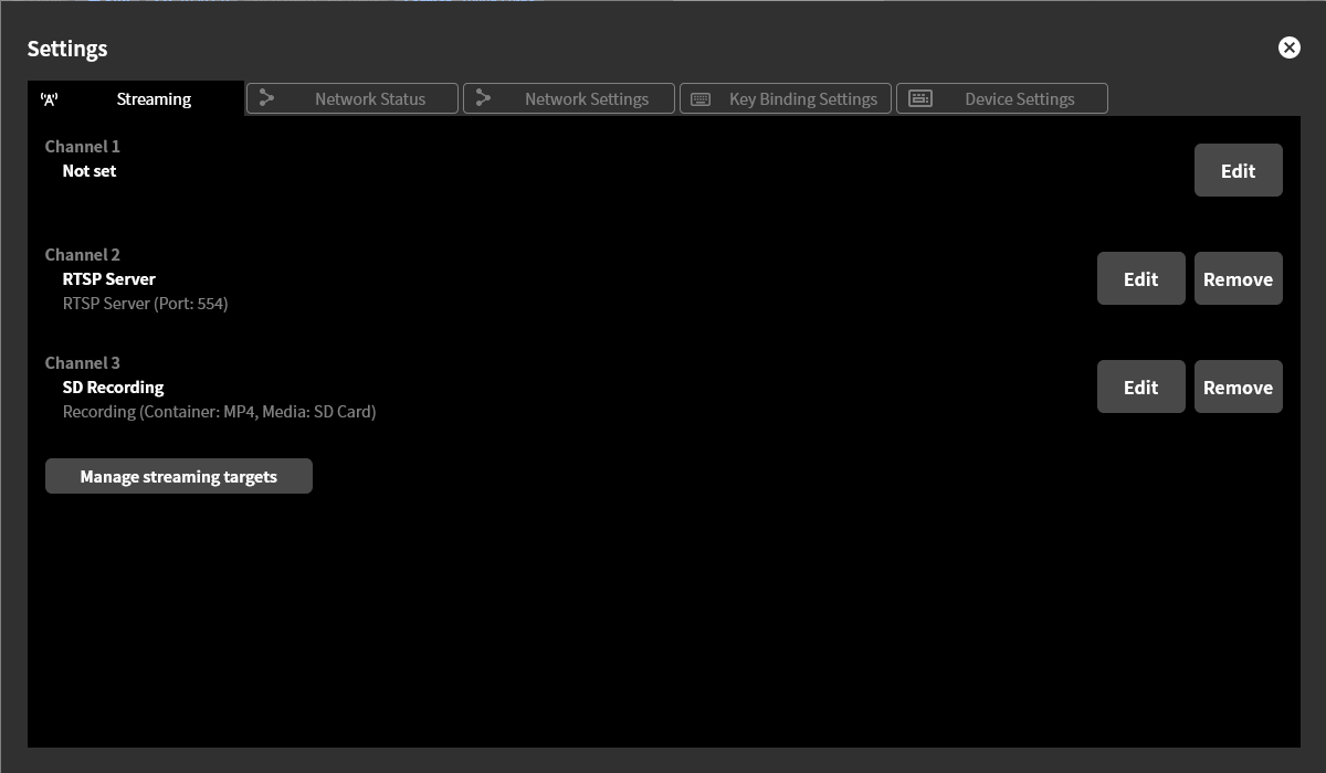
Click “+ New target”.
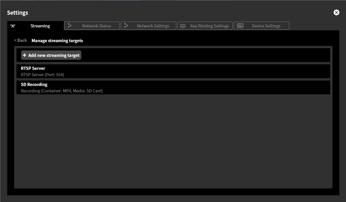
Enter the setting values on the screen that appears, then click “Save”.
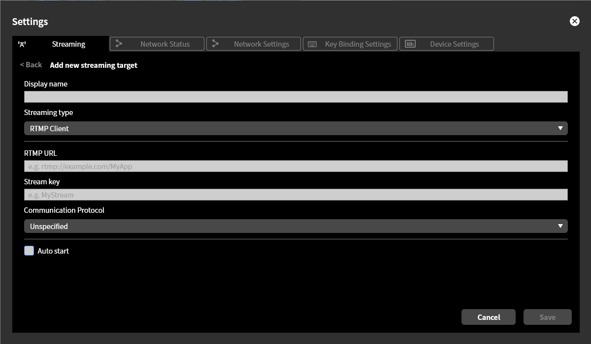
The setting values to be entered vary depending on the target type setting. Refer to the individual procedures below for each.
For RTMP clients RTMP clients
For RTSP servers RTSP server setting
For recording Live streaming recording destination setting
For MPEG2-TS over UDP MPEG2-TS over UDP setting
When you click the “Select” button for the created target, that target is selected as the target to use for the channel chosen in step 2.
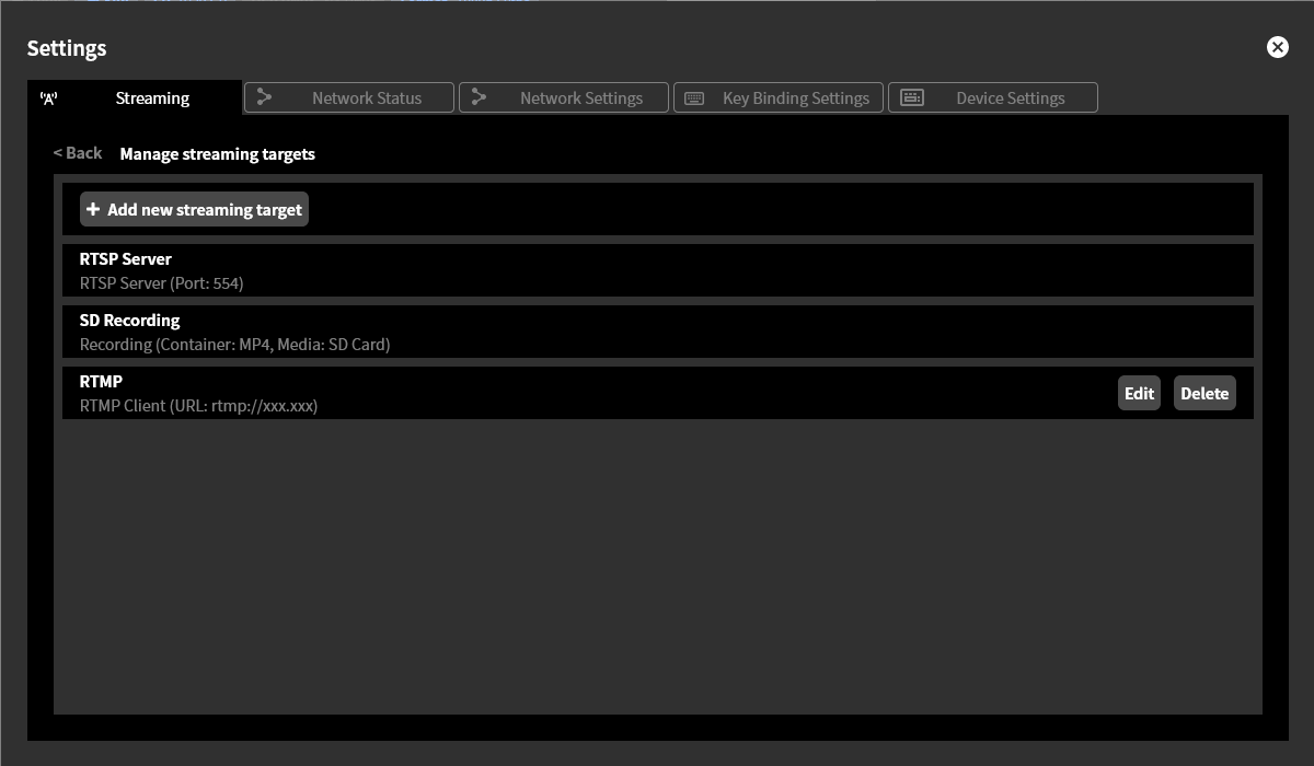
Settings for each target type
RTMP clients
For the target type “RTMP Client”, the following items must be configured.
In “Display Name”, enter any name you like (e.g., ExampleTube). The content entered here is not reflected in the actual live streaming platform and is used only for display within this product.
In “RTMP URL”, enter the RTMP URL obtained from the streaming platform. The following are examples of possible entries.
To use the default port 1935/tcp with plaintext RTMP
rtmp://rtmp.example.jp/liveTo explicitly specify port 11935/tcp with plaintext RTMP
rtmp://rtmp.example.jp:11935/liveTo use the default port 443/tcp with TLS-encrypted RTMP
rtmps://rtmp.example.jp/live
In the “Stream Key” field, enter the stream key obtained from the streaming platform.
Check “Use RTMP authentication” when connecting to an RTMP server that requires authentication with a username and password. When checked, the following additional setting items are displayed. When unchecked, they are hidden.
In “RTMP Username”, enter the username to send during authentication.
In “RTMP Password”, enter the password to send during authentication.
In “Communication Protocol”, specify the network layer protocol. You can specify Unspecified, IPv4 only, or IPv6 only.
If “Unspecified” is selected, name resolution of the host name in the RTMP URL is performed first. If AAAA records are obtained, AAAA records are given priority and an IPv6 connection is attempted. If connection to all IPv6 hosts fails, an IPv4 connection to that host is attempted if an A record exists.
If “IPv4 only” is selected, name resolution of the host name in the RTMP URL is performed first, and using only A records, an IPv4 connection to that host is attempted.
If “IPv6 only” is selected, name resolution of the host name in the RTMP URL is performed first, and using only AAAA records, an IPv6 connection to that host is attempted.
If “Auto Start” ☑ is checked, streaming to this target starts automatically when this product is booted.
RTSP server setting
For the target type “RTSP Server”, the following items must be configured.
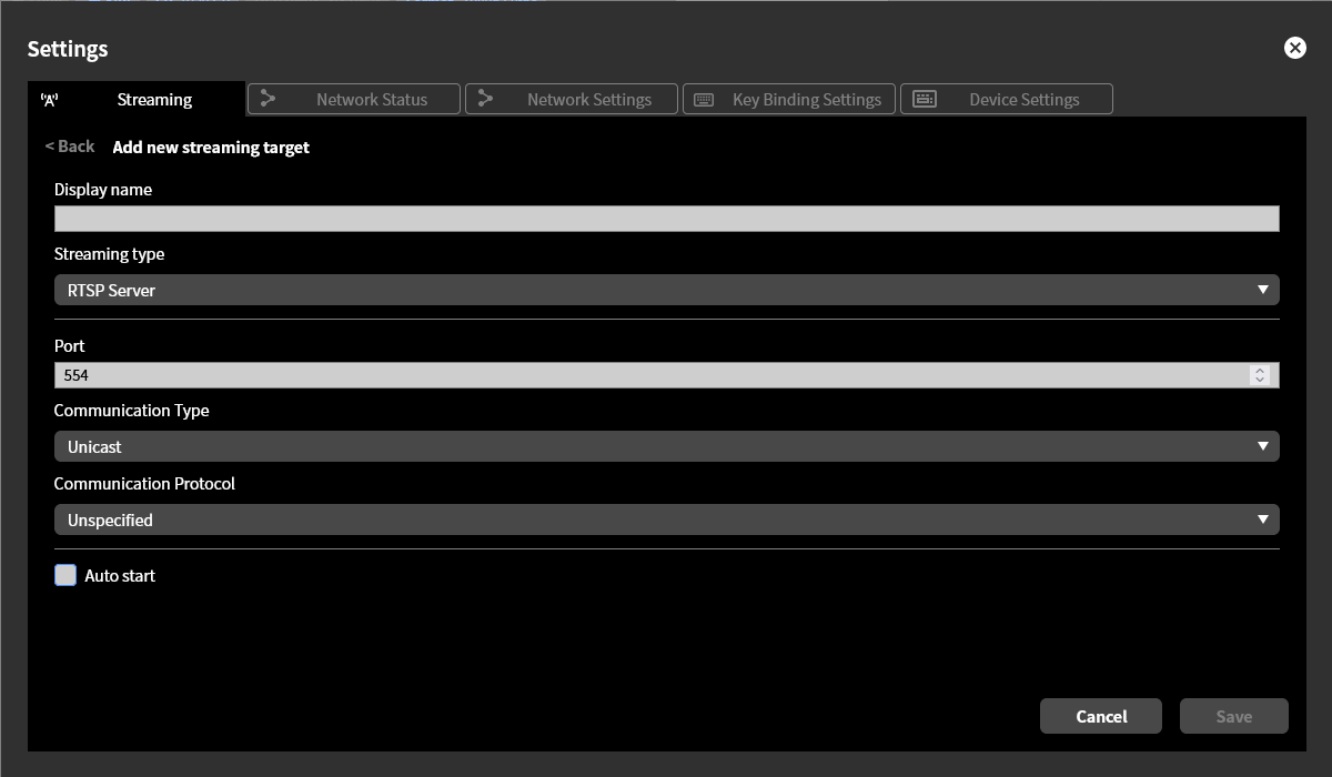
In “Display Name”, enter any name you like (e.g., RTSP Server). The content entered here is not reflected in the actual live streaming platform and is used only for display within this product.
In “Port”, enter the TCP port that the RTSP server listens on. Normally, use 554.
In “Communication method”, select whether to send media packets via unicast or multicast. Normally, select “Unicast”.
“Communication Protocol” specifies the network layer protocol. You can specify Unspecified, IPv4 only, or IPv6 only.
If “Unspecified” is selected, it listens on both IPv4 and IPv6 addresses.
If “IPv4 only” is selected, it listens on IPv4 addresses only.
If “IPv6 only” is selected, it listens on IPv6 addresses only.
If “Auto Start” ☑ is checked, the RTSP server starts automatically when this product is booted.
You cannot set an RTSP server for multiple channels. Only one channel can be set as an RTSP server.
Live streaming recording destination setting
For the target type “Recording”, the following items must be configured.
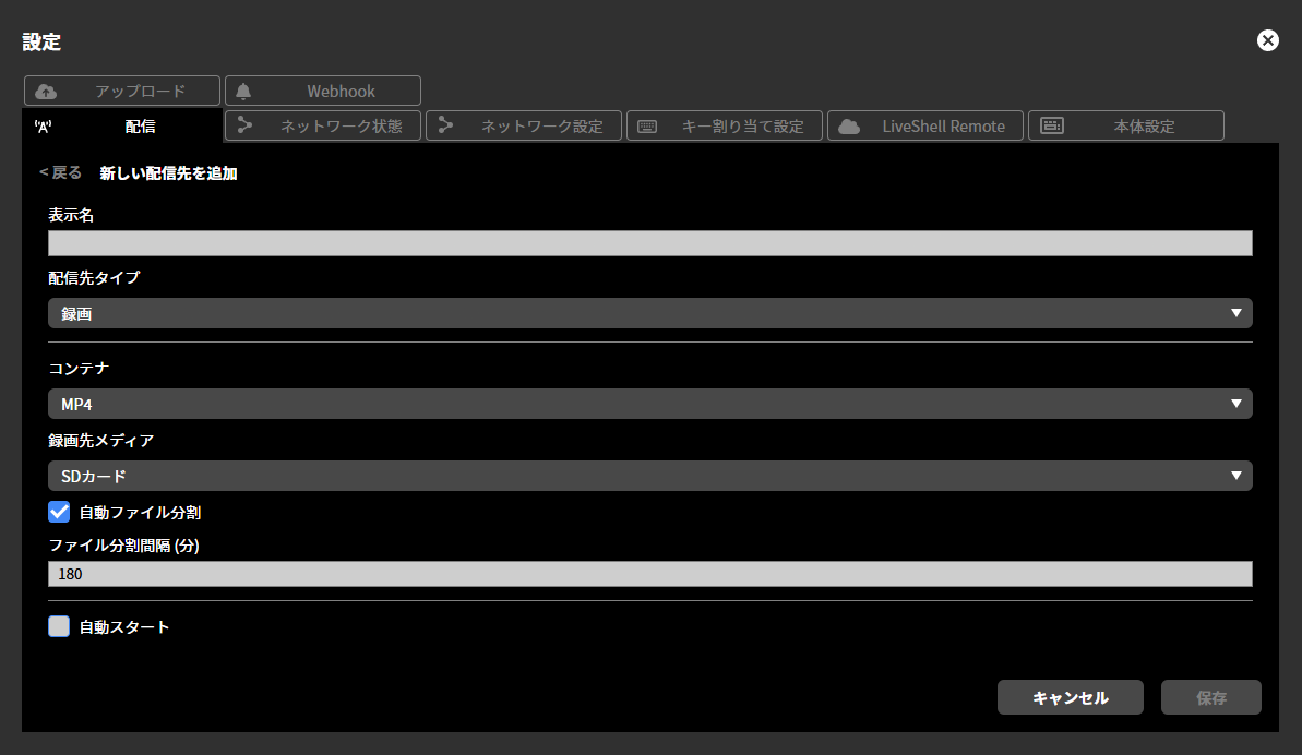
In “Display Name”, enter any name you like (e.g., Recording). The content entered here is not reflected in the actual recording file name and is used only for display within this product.
In “Container”, specify the container format to use when saving the stream. You can select either “MP4” or “MPEG2-TS”.
In “Destination Media,” specify the recording media to record to. You can choose either “SD Card” or “USB Drive.”
Depending on this setting, connect the recording media to the SD card slot or USB port on the front of the main unit.
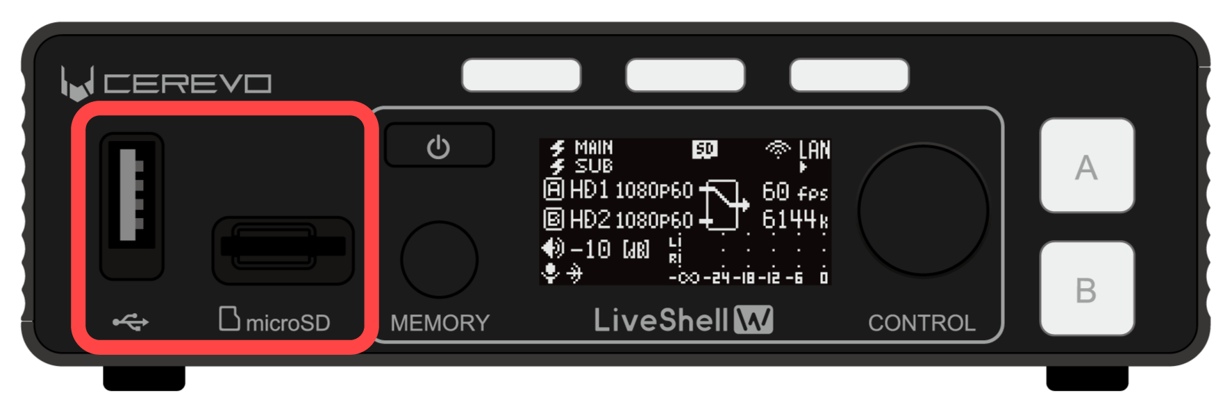
If “Automatic File Splitting” is checked, you can split the recording file at the specified time intervals. When this function is enabled, the recording file is automatically uploaded when it is split. To use this function, configure the automatic recording file upload function in advance.
If “Auto Start” is checked, recording starts automatically when this product is booted.
You cannot set multiple channels to record. Only one channel can be set to record.
MPEG2-TS over UDP setting
For the target type “MPEG2-TS over UDP”, the following items must be configured.
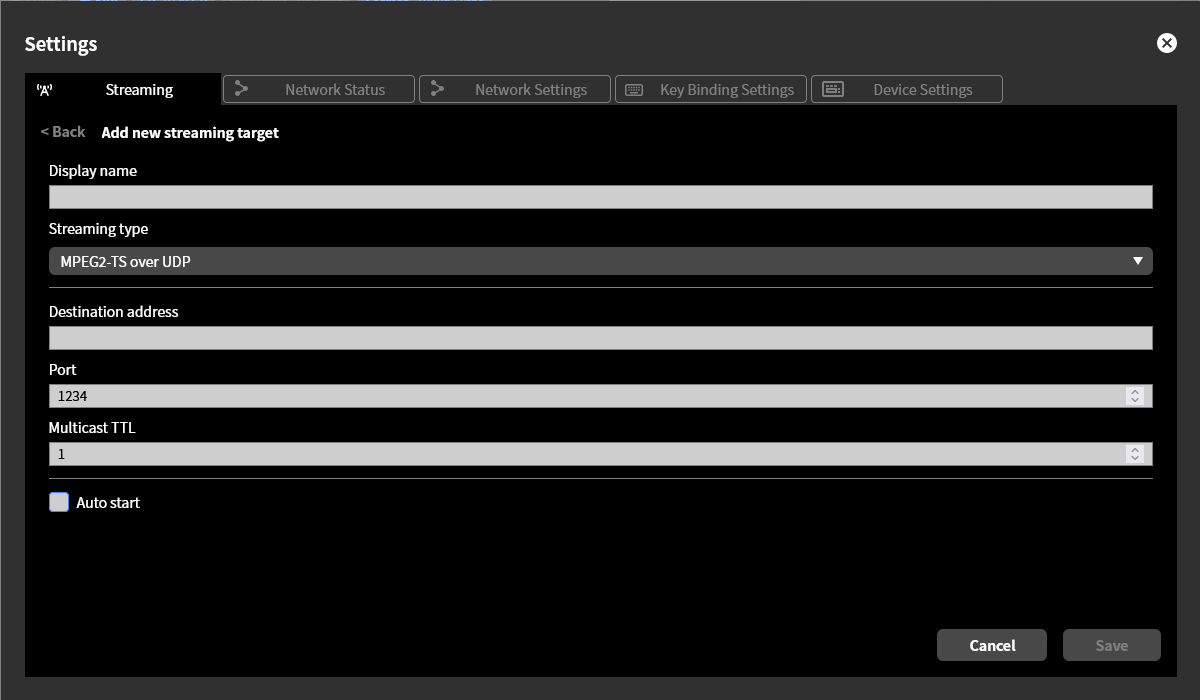
In “Display Name”, enter any name you like (e.g., UDP). The content entered here is not reflected in the actual live streaming platform and is used only for display within this product.
In “Destination Address,” enter the destination IP address to which the UDP datagram will be sent.
In “Port Number,” enter the destination port number for the UDP datagram to be sent.
In “Multicast TTL”, specify the Time To Live value used when performing multicast distribution.
If “Auto Start” is checked, streaming to this target starts automatically when this product is booted.
Changing and deleting streaming channels
To change or delete the target set for a channel, follow the steps below.
Click the gear icon at the top of the program output screen.
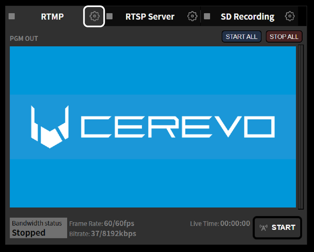
To change the target set for a channel, click the “Change” button on the settings screen that appears. In this example, Channel 1 is selected.
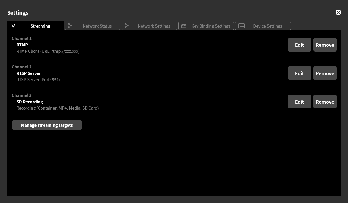
A list of targets is displayed; select the target to newly set for the channel (→Basic operation of target settings).
To delete the target set for a channel, click the “Delete” button on the settings screen that appears. In this example, Channel 1 is selected.
When you delete a streaming channel’s settings, that channel’s settings become “Unconfigured”. However, the target settings are not deleted. To edit or delete the target settings, follow the procedure in Editing and deleting target settings.
You cannot change or delete the settings of a channel that is streaming. Perform this operation after stopping the streaming.
Editing and deleting target settings
To edit or delete a target’s settings, follow the steps below.
Click the gear icon at the top of the program output screen.
Click the “Manage targets” button.
Click the “Change” or “Delete” button for the target you want to edit or delete.
When editing, configure the settings according to the target type (→Settings for each target type).
A target that is in use as a channel setting cannot be deleted. Perform this operation after removing the target from the channel (→Changing and deleting streaming channels).
Starting and stopping streaming or recording
To start and stop streaming or recording for a configured channel, follow the steps below. This operation can be performed using either LiveShell Studio or the buttons on the main unit.
Starting streaming or recording
Among the channel tabs at the top of the program output screen, click the one you want to operate.
Click the “Start Streaming” or “Start Recording” button displayed in the lower right.
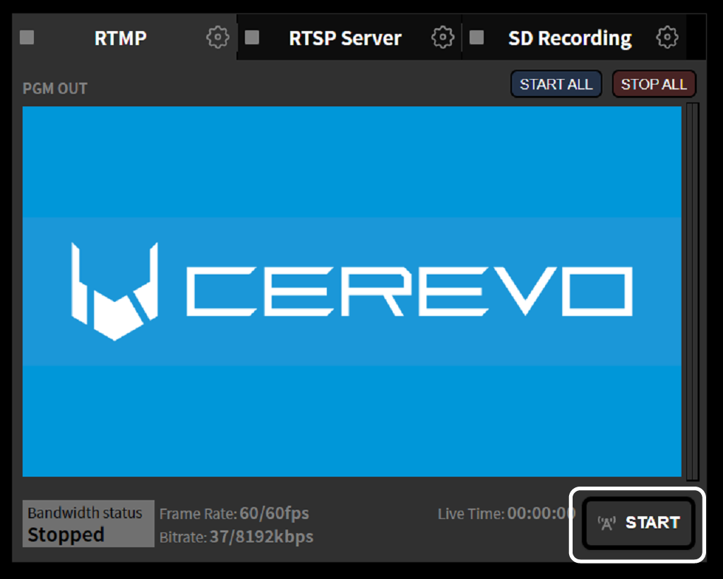
To operate all channels at once, click the “START ALL” button.
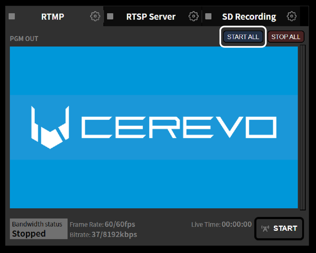
Stopping streaming or recording
Among the channel tabs at the top of the program output screen, click the one you want to operate.
Click the “Stop Streaming” or “Stop Recording” button displayed in the lower right.
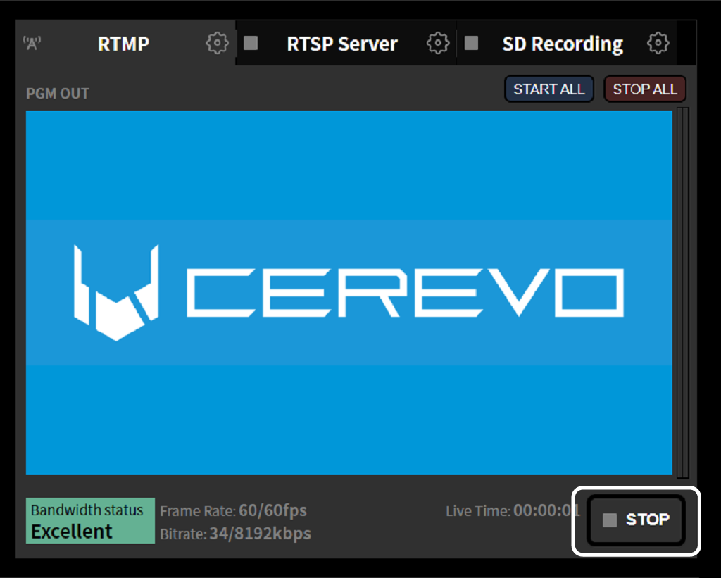
To operate all channels at once, click the “STOP ALL” button.
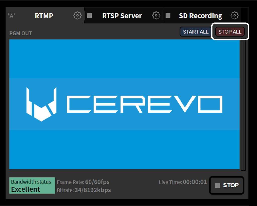
Checking the streaming status using buttons on the main unit
Streaming indicator
The “3 Stream Button Indicators” on the front of the unit light up as follows according to the streaming status of each channel.

Unlit: Indicates that the channel is not streaming or recording.
Blue: Indicates that the channel is streaming.
White: Indicates that the channel is recording.
Displaying the streaming status
Pushing one of the “3 Stream Button Indicators” once on the main status screen displays the streaming status of the selected channel on the main unit display. If non-ASCII characters are entered as the “Display Name” in the streaming destination settings, they will not be displayed correctly.
Operating streaming or recording using buttons on the main unit
You can start and stop streaming or recording by pushing one of the 3 Stream Button Indicators.
From the main status screen, push one of the “3 Stream Button Indicators” once to display the streaming status of the selected channel.
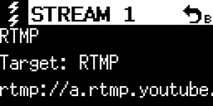
If the selected channel is stopped, pushing the same button one more time on the streaming status screen displays the start dialog. Pressing “Video Select Button A” starts streaming or recording.
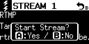
If the selected channel is currently streaming or recording, pushing the same button one more time on the streaming status screen displays the stop dialog. Pressing “Video Select Button A” stops streaming or recording.
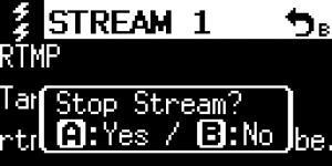
Convenient operating methods
Memory function
The Memory function is a mechanism for saving settings such as the switcher state, audio mixer adjustments, and whether a text overlay is applied as a set, then recalling the saved preset with a simple operation to apply those settings. Using the Memory function, you can perform operations such as the following:
Set up switching and transitions for each scene in advance, and apply them as the program progresses.
Prepare a text overlay to apply for each scene, and apply it as the program progresses.
Change the audio mixer level only while a performer is speaking, then return it to its original level.
Prepare a cover image and overlay it when a problem occurs.
Creating a memory setting
To use the Memory function, you must first create a memory setting and edit and save the preset contents. This can be done on LiveShell Studio. To create a new memory setting, perform the following steps.
First, select the “Memory” tab.
In the factory default state, three memory settings, “Default”, “PiP”, and “Seminar”, are pre-registered as setting examples. These settings can also be re-edited or deleted (in which case they cannot be restored to their initial state unless you perform a factory reset).
Clicking the “Create New” button at the bottom displays the memory edit screen. In its initial state, its content is set to “do nothing”.
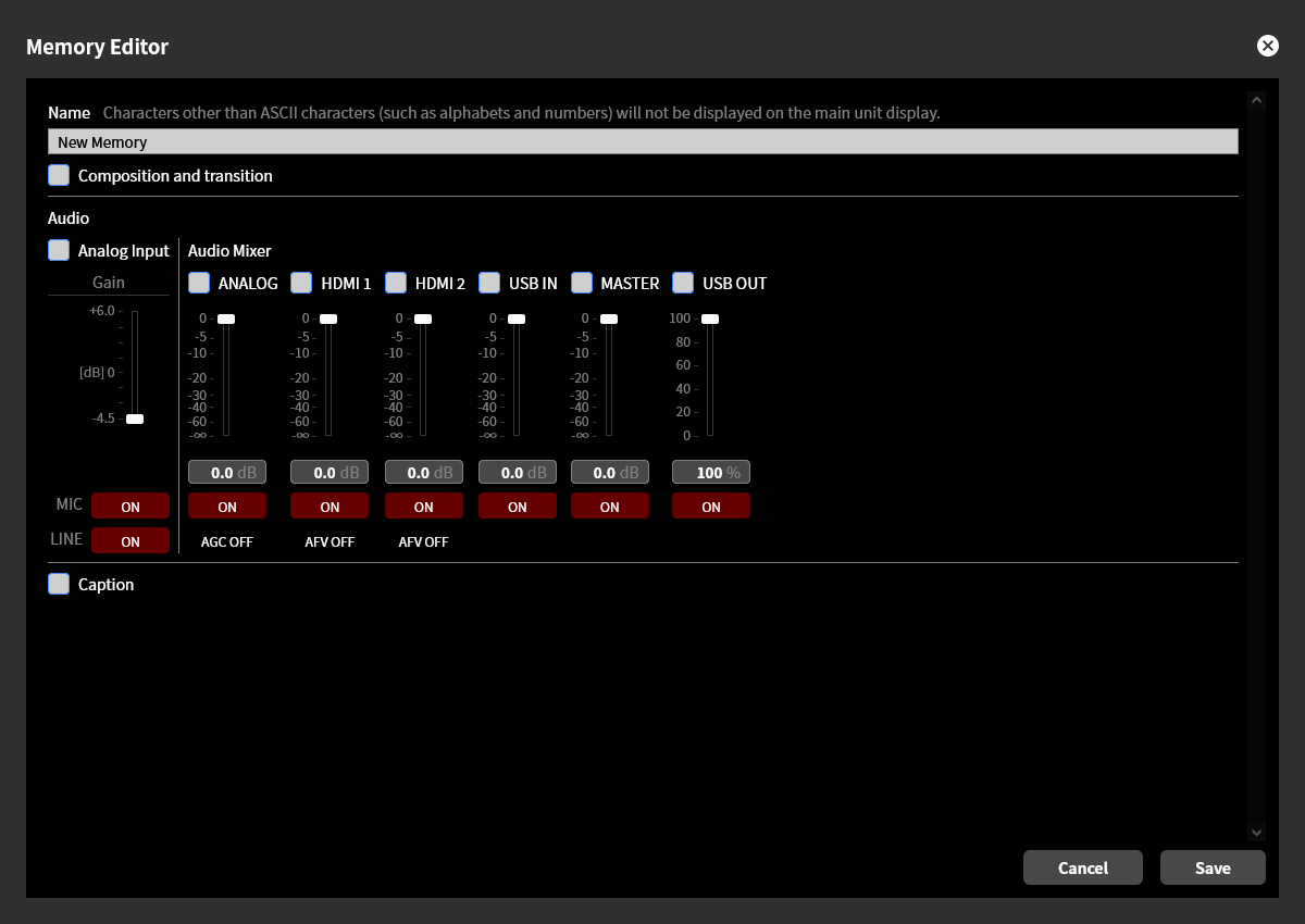
You can give a memory setting any name you like. The name of a newly created memory is “New Memory”. However, characters other than ASCII characters (such as letters and numbers) are not displayed correctly on the main unit screen. We recommend using only ASCII characters for the name.
Memory settings can be recalled using LiveShell Studio or the buttons on the main unit, as well as using external devices such as the separately sold LiveShell ControlPad or a USB keyboard.
Tip
Customizing the key assignments lets you recall memory settings more conveniently. →Key Assignment
Selecting the items to set
When editing a memory setting, you can create a preset with the desired content by using the checkboxes to select the target items that will actually take effect when the memory setting is recalled, and setting their specific values. The main items that can be selected as targets are as follows:
Composition and transition
Audio settings
Text overlay
If you select multiple items, those settings are updated simultaneously when the memory setting is recalled. Therefore, you can create presets that, for example, “switch the video source and adjust the audio mixer gain at once”, or “apply video composition and a text overlay at once”. For items not selected as targets, their state is not updated, and the state immediately before the memory setting was recalled is carried over unchanged after the recall.
The settings for “Composition and transition” and “Text overlay” are not displayed when their checkboxes are off. The display when both are turned on is shown below (depending on the screen size, scrolling may be required).
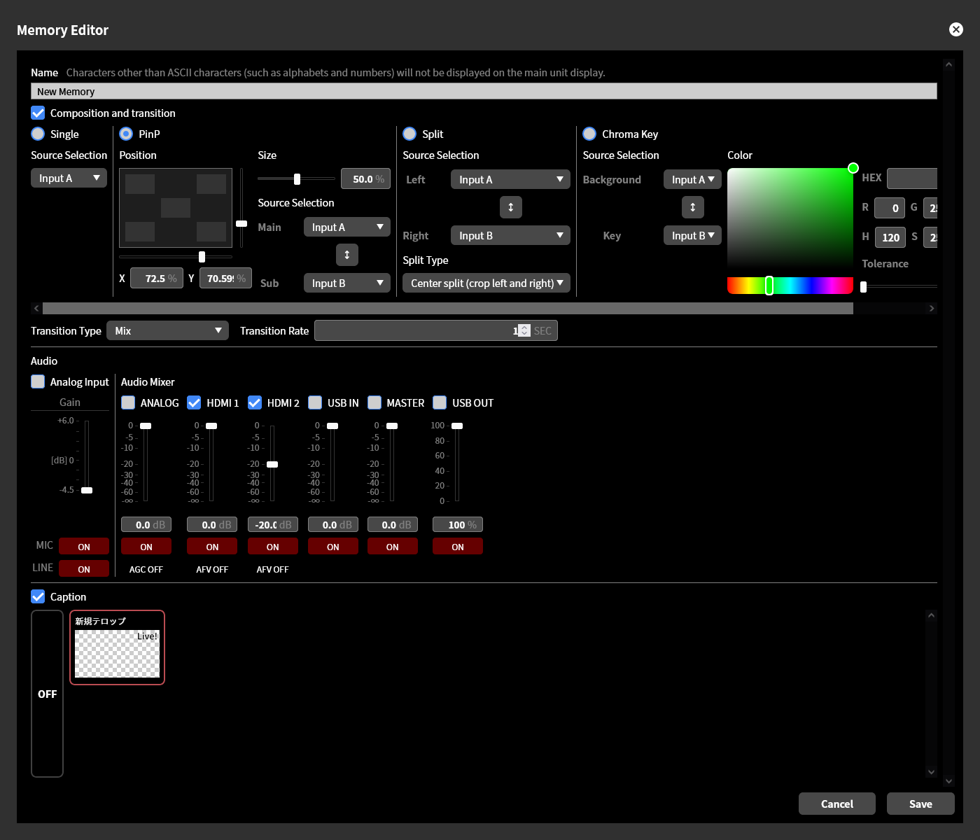
Composition and transition settings
If you want to update the video switching or composition state when the memory setting is recalled, turn on the “Composition and transition” checkbox and set the state after switching and the video effect to apply at the time of switching. This way, the specified transition is performed when the preset is applied.
The switching state can be selected from “No composition”, “PinP”, “Split”, or “Chroma Key”. For details on each setting, refer to the following.
Also, set the video effect to apply at the time of switching using “Transition Type” and “Transition Time”.
Audio settings
If you want to update the analog input gain when the memory setting is recalled, turn on the “Analog input” checkbox and set the analog audio input gain and the analog audio input mute state.
→Analog audio input gain adjustment
If you want to update the audio mixer gain and other values when the memory setting is recalled, turn on the checkbox for the channels whose values you want to update among the audio mixer channels “ANALOG”, “HDMI1”, “HDMI2”, “USB IN”, “MASTER”, and “USB OUT”, and set the gain and mute state. For the ANALOG input you can also set whether AGC is enabled, and for the HDMI inputs you can set whether AFV is enabled.
Text overlay settings
To update the text overlay application state when the memory setting is recalled, turn on the “Text overlay” checkbox and select the text overlay to apply from the list. The text overlay to be used must be created in advance.
To leave the text overlay unapplied when the memory is recalled, select “OFF”.
Re-editing a memory setting
You can re-edit a memory setting by clicking the “Edit” icon within its icon in the memory settings list. During re-editing, you can change the preset content.
Deleting a memory setting
You can delete a memory setting by clicking the “Trash” icon within its icon in the memory settings list. Once deleted, a memory setting cannot be restored.
Duplicating a memory setting
Clicking the “Duplicate” button within a memory setting’s icon in the memory settings list lets you create a new memory setting that duplicates that memory setting. The duplicated memory setting can be re-edited, and this editing does not affect the original memory setting.
Recalling a memory setting
To recall a created memory setting and apply its preset content, perform the following steps.
Operation in LiveShell Studio
First, select the “Memory” tab.
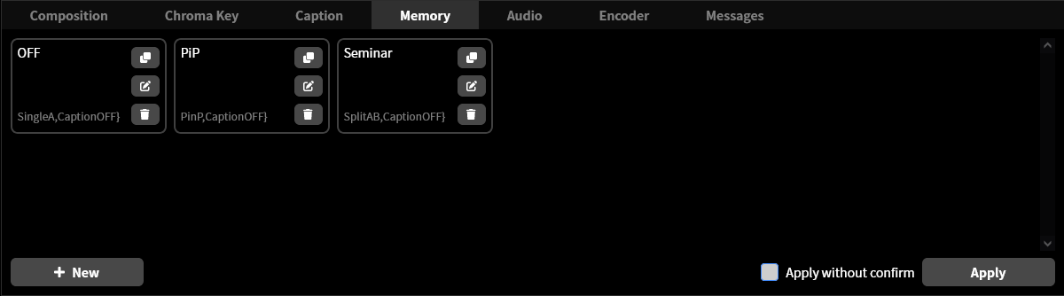
Select the one you want to recall from the icons in the memory settings list, and click the “Apply” button.
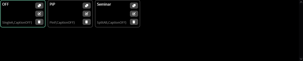
If you want to recall memory settings quickly, turn on the “Apply without confirmation” checkbox. In this case, simply clicking a memory setting’s icon recalls and applies that memory setting, and clicking the “Apply” button is no longer required.
Operation using buttons on the main unit
Pressing the MEMORY button on the main unit switches the display to memory mode, allowing you to recall the saved memory settings. To exit memory mode and return to the main menu, press the B button or the power button.
From the list of saved memory settings, use the control dial to select the memory setting you want to recall.
Pressing the control dial while a memory setting is selected recalls and applies that memory setting.
In memory mode, selecting the audio mixer icon takes you to the audio mixer settings screen. To return from the audio mixer to the memory recall screen, press the B button.
Operation using the ControlPad
Using Key Assignment, you can recall memory settings by pressing the buttons on the separately sold ControlPad. In the factory default settings, pressing button 1 recalls the “Default” memory setting, button 2 recalls “PiP”, and button 3 recalls “Seminar”.
Operation using a USB keyboard, etc.
Using Key Assignment, you can recall memory settings by key operations on a commercially available USB keyboard, etc.
Tip
When you recall a memory by operating an input device such as the ControlPad or a USB keyboard, which memory setting was selected is also displayed on the main unit screen. Use this as an operation confirmation display.
Startup memory setting
Configuring the startup memory lets you automatically apply a specific memory when this product starts up.
To set up a name, follow the steps below.
This operation can be performed from LiveShell Studio. It cannot be set on the unit button operation.
Press “Startup memory” displayed within the “Memory” tab.
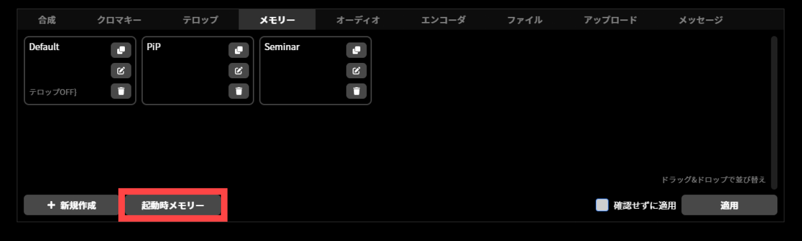
The “Set startup memory” dialog is displayed. Select the memory item to recall at unit startup from the pull-down menu.
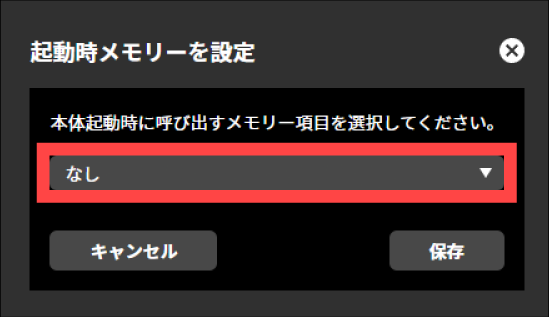
Press “Save”.
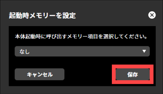
Key Assignment
The key assignment settings are a function for customizing how this product is operated to suit the conditions of the site where it is used and your preferences. By configuring the key assignments, you can operate this product using the separately sold LiveShell ControlPad (hereafter referred to as the “Control Pad”) or a USB keyboard. In addition, by customizing the functions assigned to the buttons and the control dial on the main unit, you can assign your own functions that differ from the standard ones.
The following are examples of operability that can be achieved using the key assignment settings.
Recall a memory using the “A” or “B” button on the main unit to control the video composition state.
Recall a memory using the “A” or “B” button on the main unit to insert a text overlay as a cover image.
Turn the control dial while holding down the “A” button on the main unit to adjust the audio mixer gain.
Recall memory settings using the Control Pad or a USB keyboard.
Adjust the audio mixer gain using the dial on the Control Pad.
How to configure in LiveShell Studio
The key assignment settings can be configured from LiveShell Studio. In LiveShell Studio, click “Settings” and select the “Key assignment settings” tab.
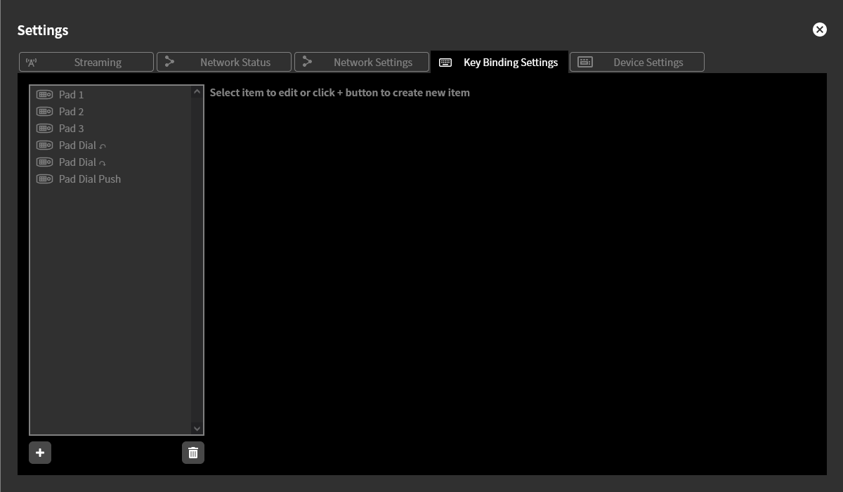
The list on the left side of the screen displays the configured key assignment settings. In the factory default state, the key assignment settings “Pad 1”, “Pad 2”, “Pad 3”, “Pad dial counterclockwise”, “Pad dial clockwise”, and “Pad dial press” are registered as initial settings. These are the settings that correspond to the separately sold Control Pad. These initial settings can also be re-edited or deleted. However, restoring the initial settings requires a factory reset.
The concept of key assignment settings
A key assignment setting is defined by first specifying a “key trigger” and then selecting an “action” for it.
Key trigger
A key trigger is the definition of an operation performed by the operator, such as pressing a button on the main unit, pressing a key on the keyboard, or turning the dial. When an operation matching the conditions defined as a key trigger is actually performed, the key trigger fires and the “action” defined for that key trigger is executed immediately.
Key triggers can be defined separately for operations on a USB keyboard, operations on the Control Pad, and operations using the buttons on the main unit. As a firing condition, you can specify a single key press or a turn of the dial, and you can also make a simultaneous key press the condition. In addition, you can add a long press as a condition. For example, you can define a key trigger that fires when the “A” and “B” buttons on the main unit are pressed at the same time, or a key trigger that fires when “A” is pressed while “B” is long-pressed at the same time.
Action
An action is the definition of the behavior performed in response to a key trigger. In addition to Recalling a memory setting, an action can specify primitive behaviors such as changing the audio mixer gain, switching inputs, and starting or stopping streaming. It can also be assigned as a key equivalent to a button for operating the main unit menu. If you want to perform a composite behavior in a single action, you can achieve this by first defining a memory setting and specifying its recall as the action.
Creating a new key assignment setting
Click the “+” at the bottom of the key assignment settings list to create a new key assignment setting. In a key assignment setting, you first select the input device that the key trigger applies to from “USB Keyboard”, “Control Pad”, and “Main Unit Buttons”. Depending on your selection, a different diagram is displayed for each device.
Key assignment settings for a USB keyboard
This screen lets you configure key assignment settings for operating this product with a commercially available USB keyboard connected to it. As the keyboard diagram shown for setting key triggers, you can choose between the Japanese keyboard and English keyboard key maps.
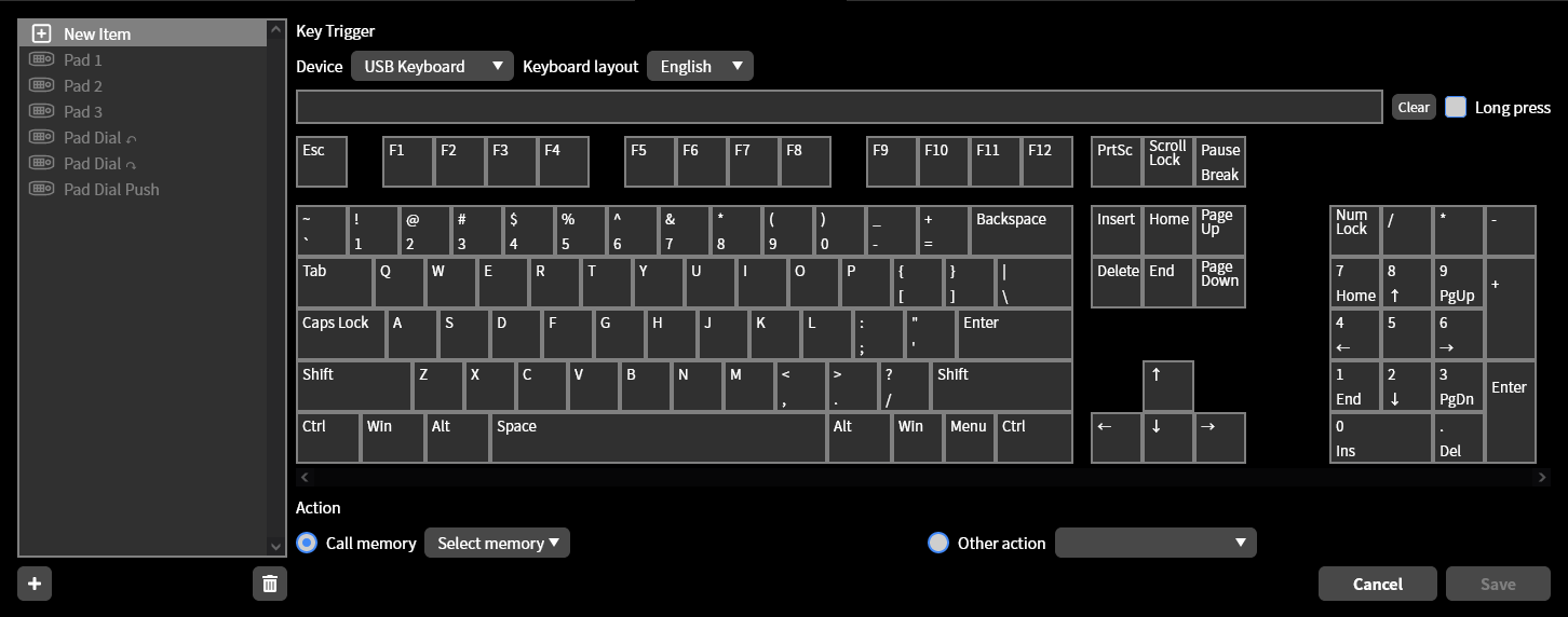
To set a key trigger, click the name of the key you want to use as the trigger condition on the keyboard diagram. The specified condition appears in the blank field below the device. If only one key is specified, the key trigger fires on a simple press of that key alone. If you then click another key while in that state, the key trigger fires when two or more keys are pressed simultaneously. You can add up to six keys to a simultaneous-press condition in the settings, but the number of simultaneously pressed keys that can actually be recognized is limited depending on the keyboard and key types used.
A key trigger with a simultaneous-press condition fires when, while holding down all keys except the last one in the condition list, you press the last key. For example, if you specify “1 + 2” as the key trigger condition, it fires when the “1” key on the keyboard is pressed first and then the “2” key is pressed. Conversely, if you specify “2 + 1” as the key trigger condition, it fires when the “2” key is pressed first and then the “1” key is pressed. Please note that these are different behaviors.
If you want to use a long press as the trigger condition, turn ON the “Long press” checkbox. If only one key is specified, the key trigger fires on a long press of that key alone. If multiple keys are specified, the key trigger fires when you long-press the last key while holding down all keys except the last one in the condition list. A long press is recognized as a continuous press of two seconds or more. A press of less than two seconds is recognized as a simple press.
To clear an entered condition, click the “Clear” button.
Key assignment settings for the control pad
This screen lets you configure key assignment settings for operating this product with the separately sold control pad connected to it.
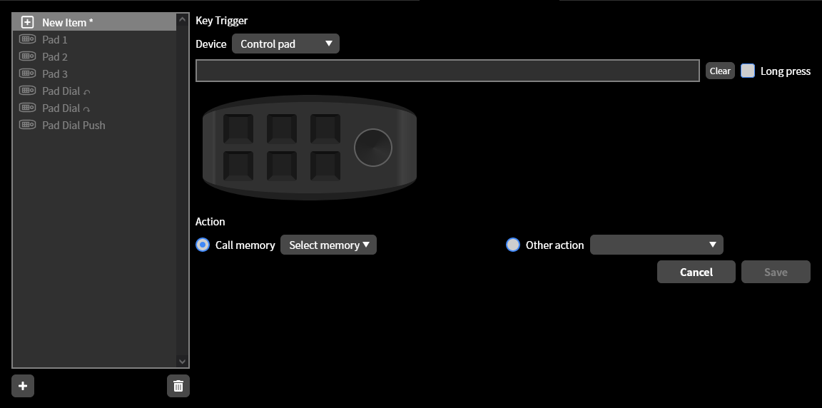
The method for setting key triggers is the same as for a USB keyboard. The difference is that the control pad has a dial. For dial operations, you can specify counterclockwise rotation, clockwise rotation, and pressing the dial in, each as a trigger condition. However, the following combinations cannot be set.
Conditions that include dial rotation where the dial rotation is not the last condition
Conditions that include dial rotation and have a long press specified
Customizing main unit button operations
This screen lets you configure key assignment settings for operating this product by customizing the button operations on the main unit of this product.
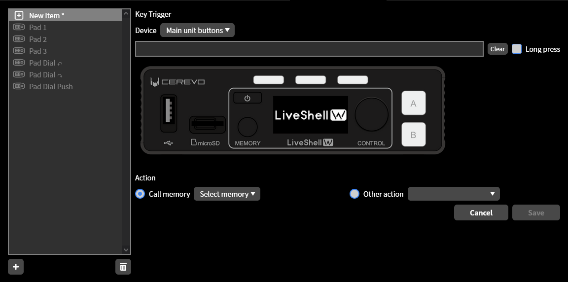
The method for setting key triggers is almost the same as for a USB keyboard and a control pad. However, for consistency with the operation of this product, there are restrictions on the conditions that can be used for key assignment settings.
The following operations are used by default as keys for operations on the status screen and in the menu, so you cannot assign other functions to them using key assignment settings. However, the operations marked with an asterisk (*) (pressing the A or B button on the status screen, and pressing the 3 streaming button indicators within the menu) can be assigned other functions only when in their respective states.
Status screen |
Within the menu |
|
|---|---|---|
Rotating the control dial |
Do nothing |
[Menu] Decrease/Increase |
Pressing the control dial |
(Main unit) Main menu |
[Menu] Select |
Pressing A |
※ A単体表示へ切り替え |
[Menu] Confirm |
Pressing B |
※ B単体表示へ切り替え |
[Menu] Back |
Pressing the 3 streaming button indicators |
(Main unit) Streaming status 1/2/3 |
※ [メニュー]何もしない |
Pressing Memory |
(Main unit) Memory |
[Menu] Switch |
Pressing Power |
Do nothing |
(Main unit) Home |
Long-pressing Power |
Power off |
Power off |
Re-editing a key assignment setting
To re-edit a key assignment setting, select the target setting from the list. You can re-edit it using the same operations as when creating a new one. Click the “Save” button to save the edited results. Click the “Cancel” button to discard the edits.
Deleting a key assignment setting
To delete a key assignment setting, select the target setting from the list and click the trash can icon. A deleted key assignment setting cannot be restored.
Useful settings
Automatic recording file upload function
Unit menu / Not configurable
LiveShell Studio / Settings →Upload
The automatic recording file upload function is a mechanism that automatically uploads recording files on the recording media inserted in this product to any server using S3, FTP, and WebDAV.
If automatic file splitting is enabled in the recording settings, the recording file is automatically uploaded when it is split. →Live streaming recording destination setting
To configure the settings for this function, follow the steps below.
This operation can be performed from LiveShell Studio. It cannot be performed on the device itself.
In LiveShell Studio, click “Settings” and select the “Upload” tab.
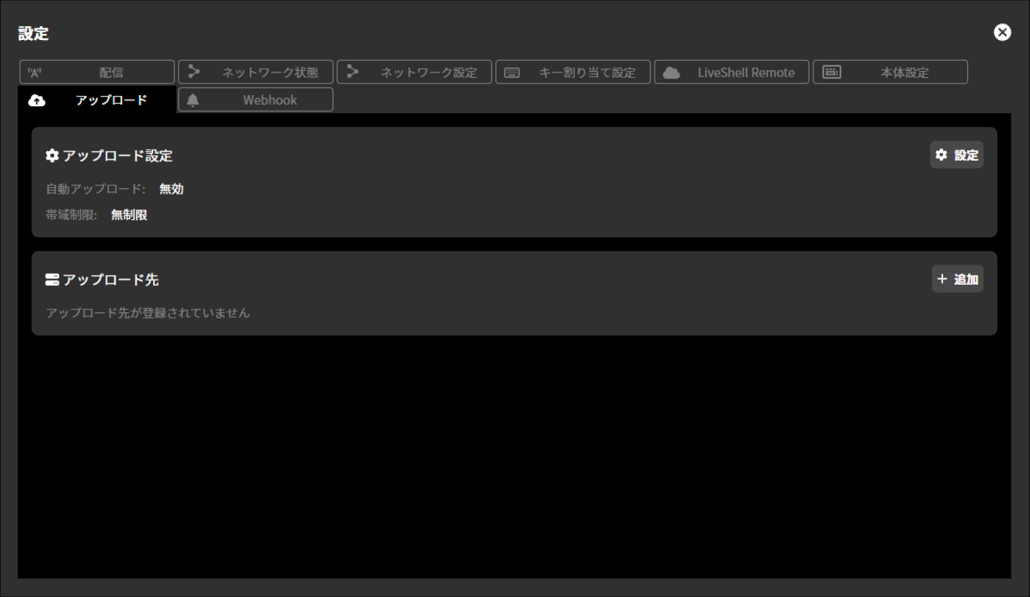
Upload settings
To configure the upload settings, follow the steps below.
Select “Settings” displayed within “Upload Settings”.
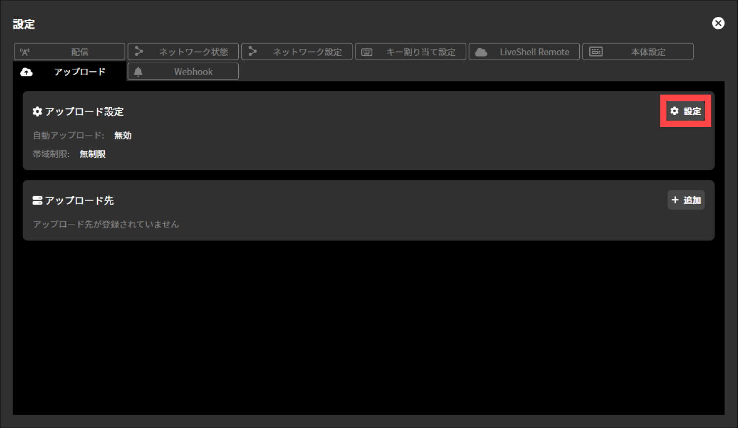
In the upload settings, you need to configure the following items.
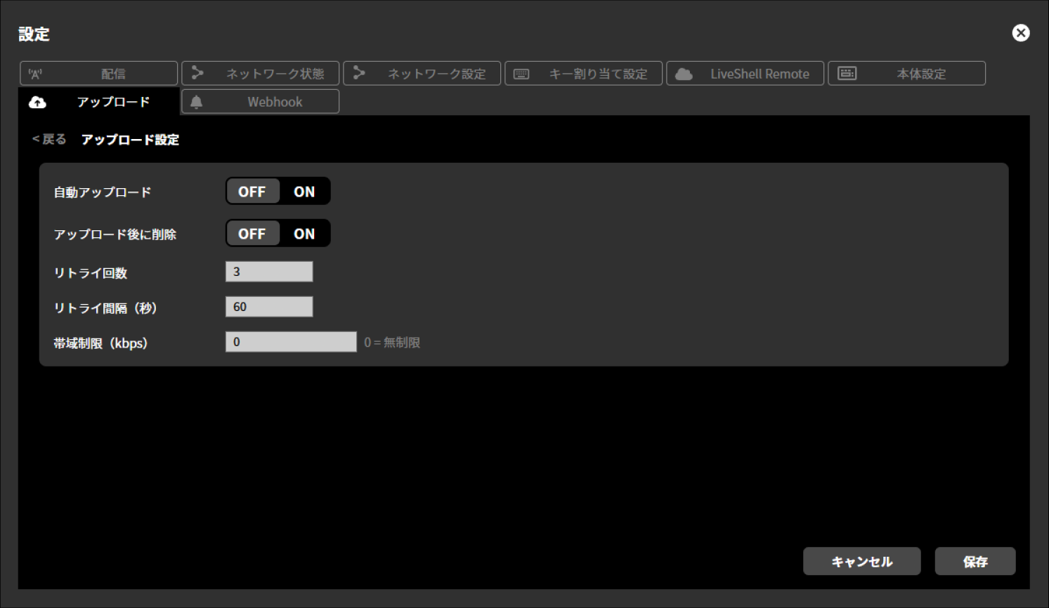
Automatic upload
You can select ON or OFF for automatic upload.
Delete after upload
You can select whether to delete the recording file after automatic upload.
Number of retries
You can set the number of retries when automatic upload fails.
Retry interval (seconds)
You can set the interval for performing the above retries. The unit of setting is seconds.
Bandwidth limit (kbps)
You can set the maximum transfer speed when uploading. The unit of setting is kbps.
Upload destination settings
To configure the upload destination settings, follow the steps below.
Select “Add” displayed within “Upload Destination”.
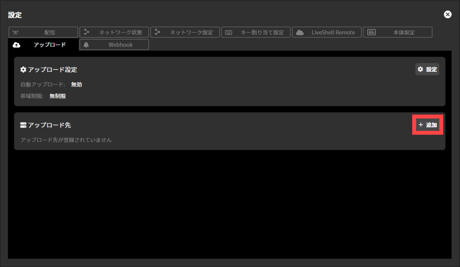
In the upload destination settings, you need to configure the following items.
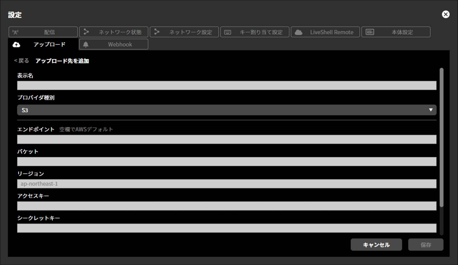
Display name
Provider type
S3
WebDAV
FTP
Some of the configurable items differ depending on the provider type. The items that can be configured for each provider type are as follows.
S3
Endpoint
Bucket
Region
Access key
Secret key
Remote path
WebDAV
Endpoint
Username
Password
Remote path
FTP
Host
Port number
Username
Password
Remote path
Use FTPS
Selected / Not selected
Use passive mode
Selected / Not selected
After configuring each item, you can perform an upload test by selecting “Test”.
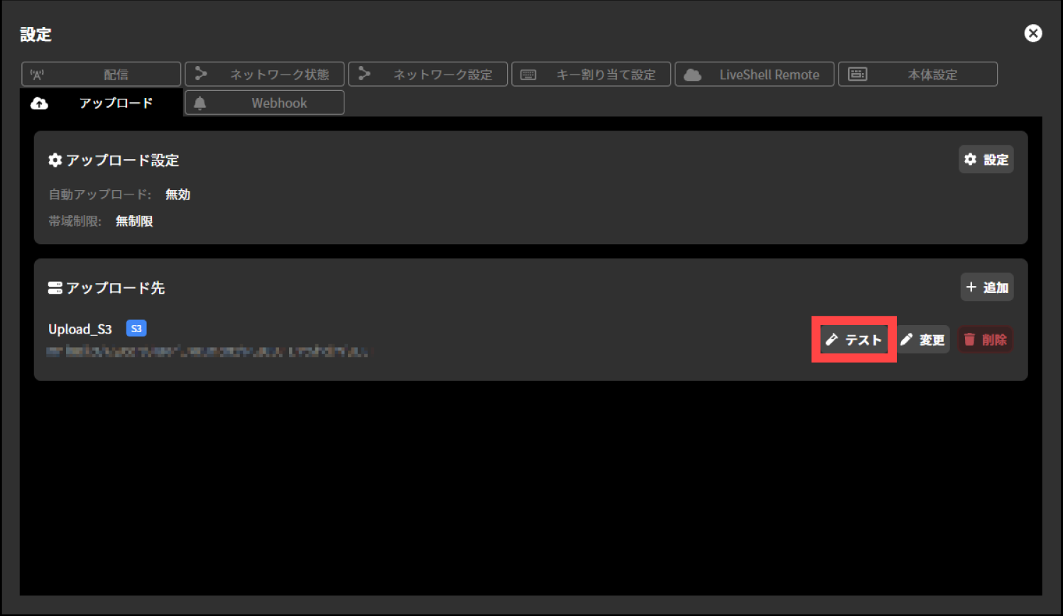
File download function for recording media
Unit menu / Not configurable
LiveShell Studio / File tab
This product allows you to download files on the connected recording media from LiveShell Studio. Note that this function cannot be operated from LiveShell Remote.
To make the setting, follow the steps below.
This operation can be performed from LiveShell Studio. It cannot be performed on the device itself.
Press the “File” tab displayed at the bottom of the top screen.
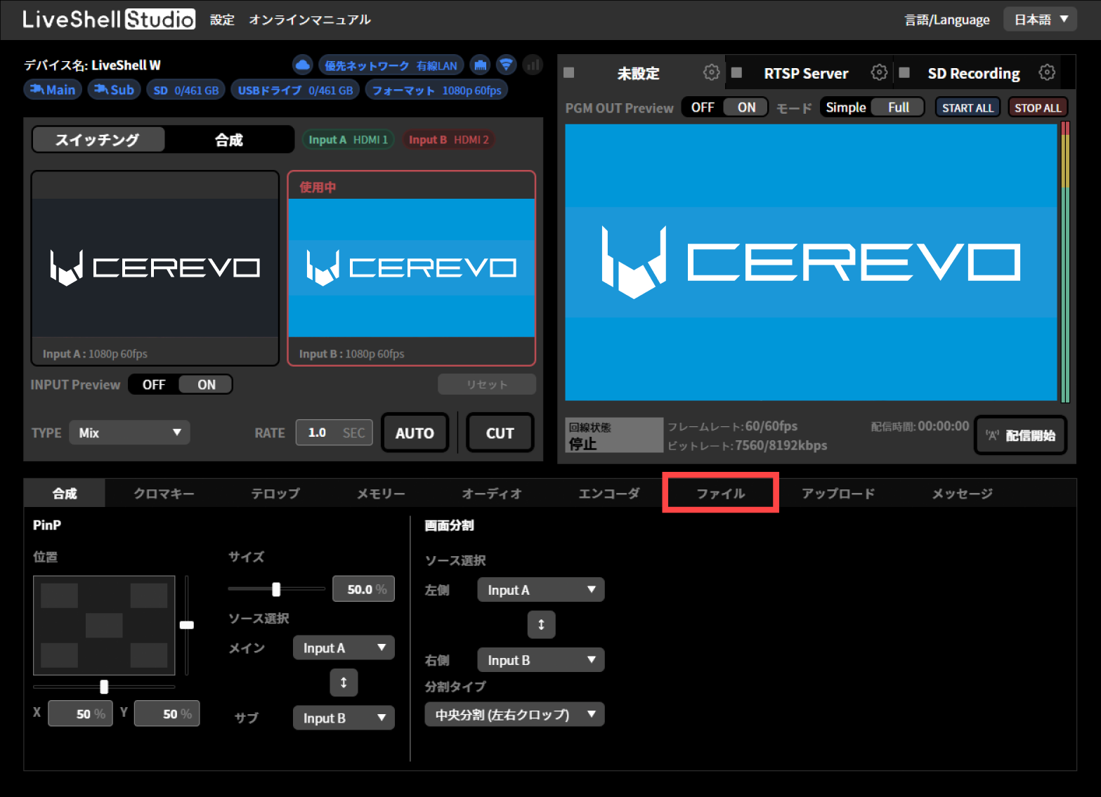
From “SD” and “USB” displayed within the “File” tab, select the recording media you want to operate.
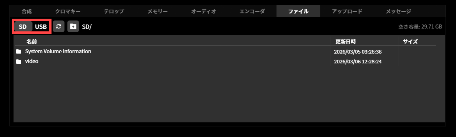
From the displayed list, hover the cursor over the file you want to download and press “Download”. To reload the recording media, press the “Refresh” button. To return to the previous folder, press the “Back” button.
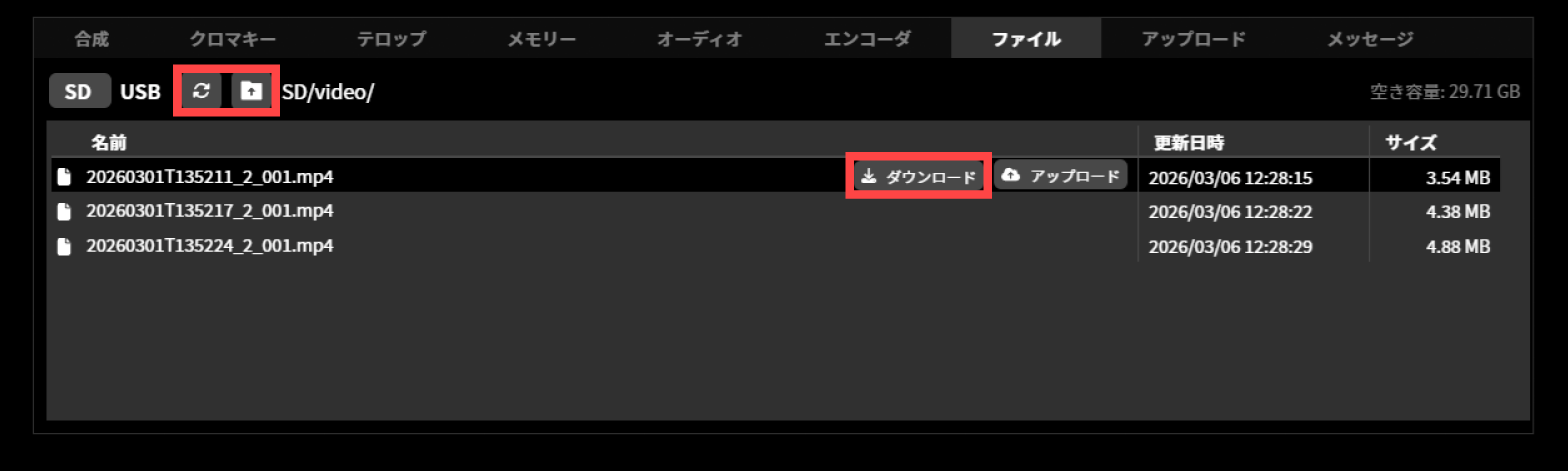
Uploading Files on a Recording Medium
Unit menu / Not configurable
LiveShell Studio / File tab
This product can upload files on the connected recording medium to any server from LiveShell Studio. To use this feature, configure the upload destination in advance. →Upload destination settings
To make the setting, follow the steps below.
This operation can be performed from LiveShell Studio. It cannot be performed on the device itself.
Press the “File” tab displayed at the bottom of the top screen.
From “SD” and “USB” displayed within the “File” tab, select the recording media you want to operate.
From the displayed list, hover the cursor over the file you want to download and press “Download”. To reload the recording media, press the “Refresh” button. To return to the previous folder, press the “Back” button.
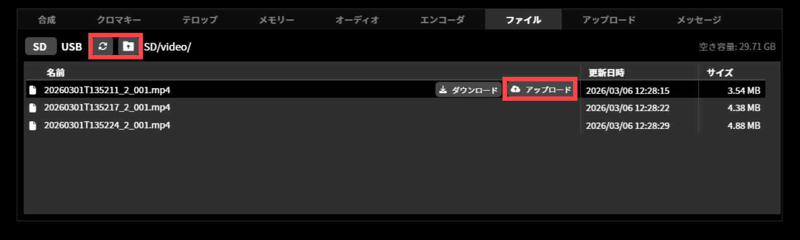
Notifications via Webhook
Unit menu / Not configurable
LiveShell Studio / Settings →Webhook tab
Using the Webhook notification feature, you can send messages via webhook to tools such as Slack and Teams on events such as startup, streaming start/stop, upload completion, and Remote connection/disconnection.
To make the setting, follow the steps below.
This operation can be performed from LiveShell Studio. It cannot be performed on the device itself.
In LiveShell Studio, click “Settings” and select the “Webhook” tab.
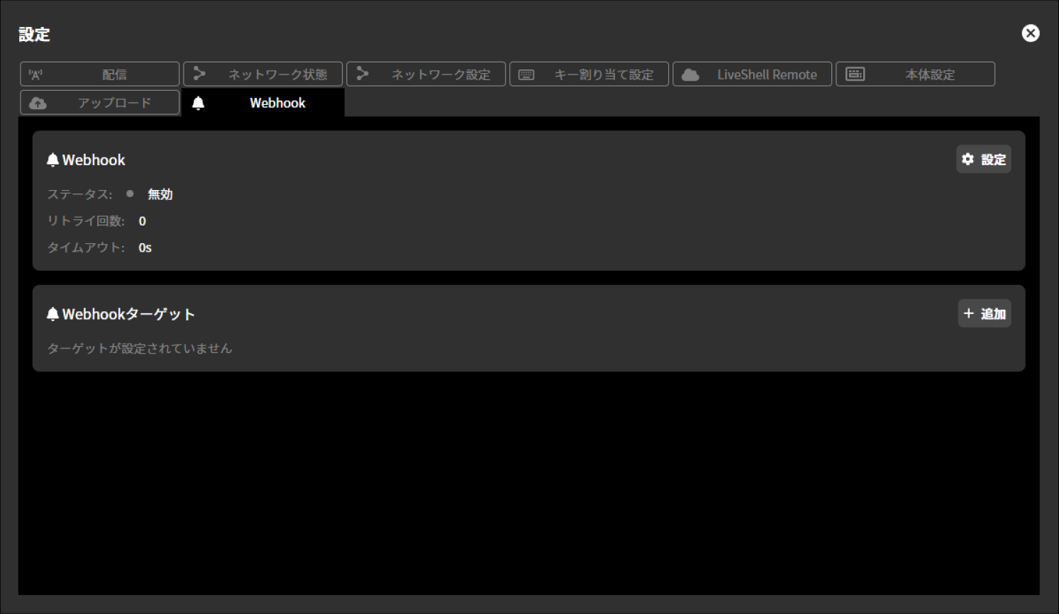
Webhook General Settings
To configure the Webhook general settings, follow the steps below.
Press “Settings” shown within “Webhook”.
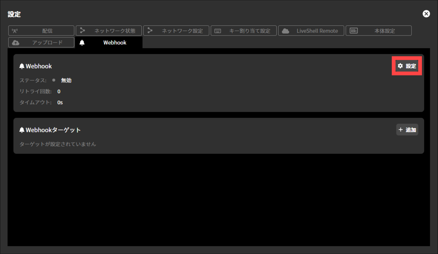
Make selections for each displayed setting and enter the desired values in the input fields. The available settings are as follows.
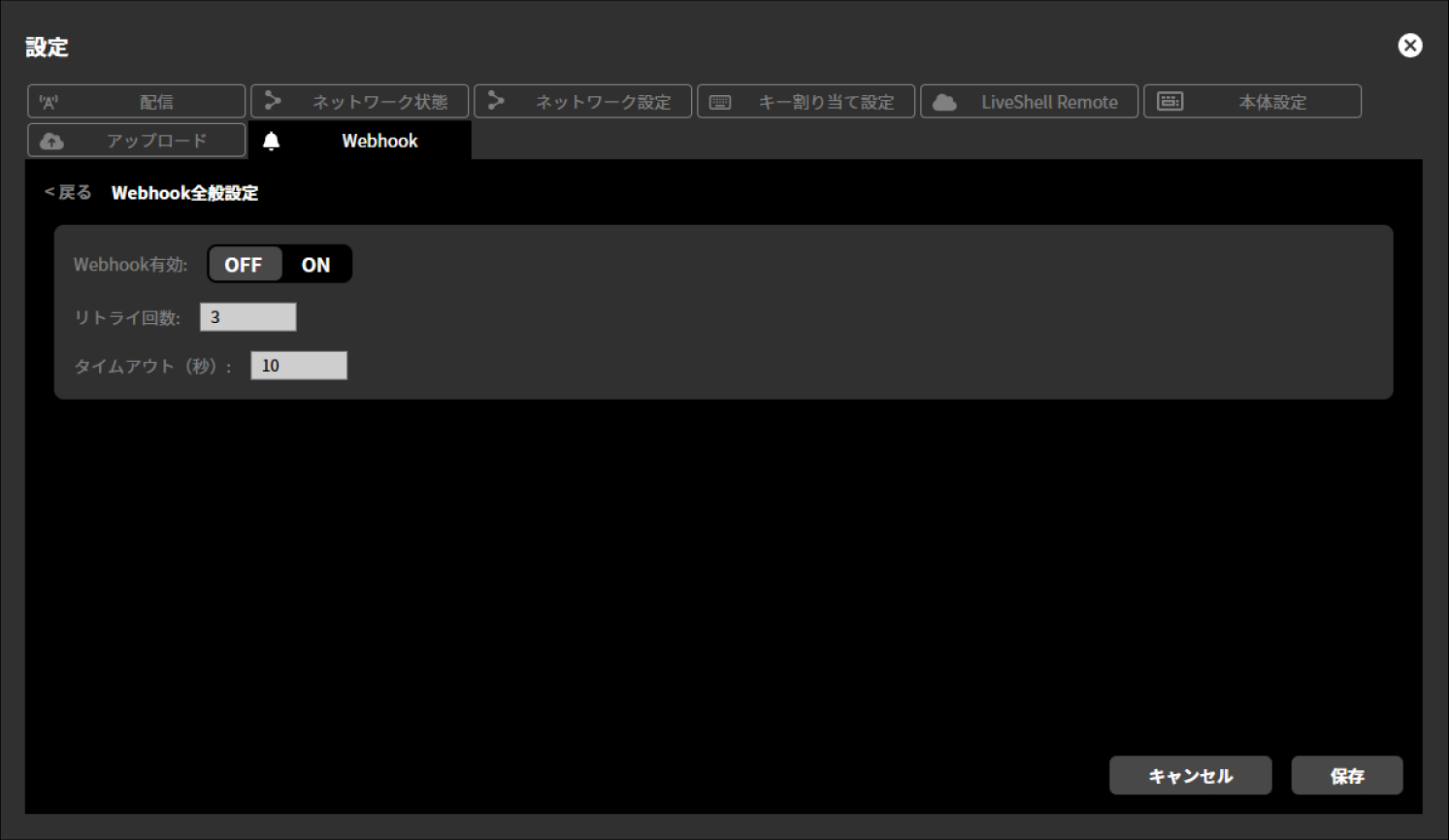
Webhook Enabled
OFF / ON
Number of retries
Timeout (seconds)
Press “Save”.
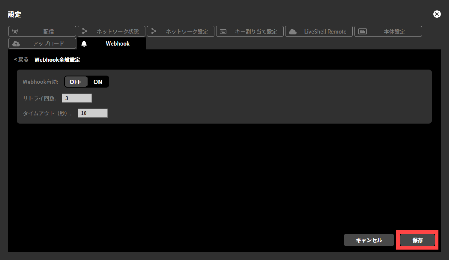
Webhook Target Settings
To configure the Webhook target settings, follow the steps below.
Press “Add” shown within “Webhook Target”.
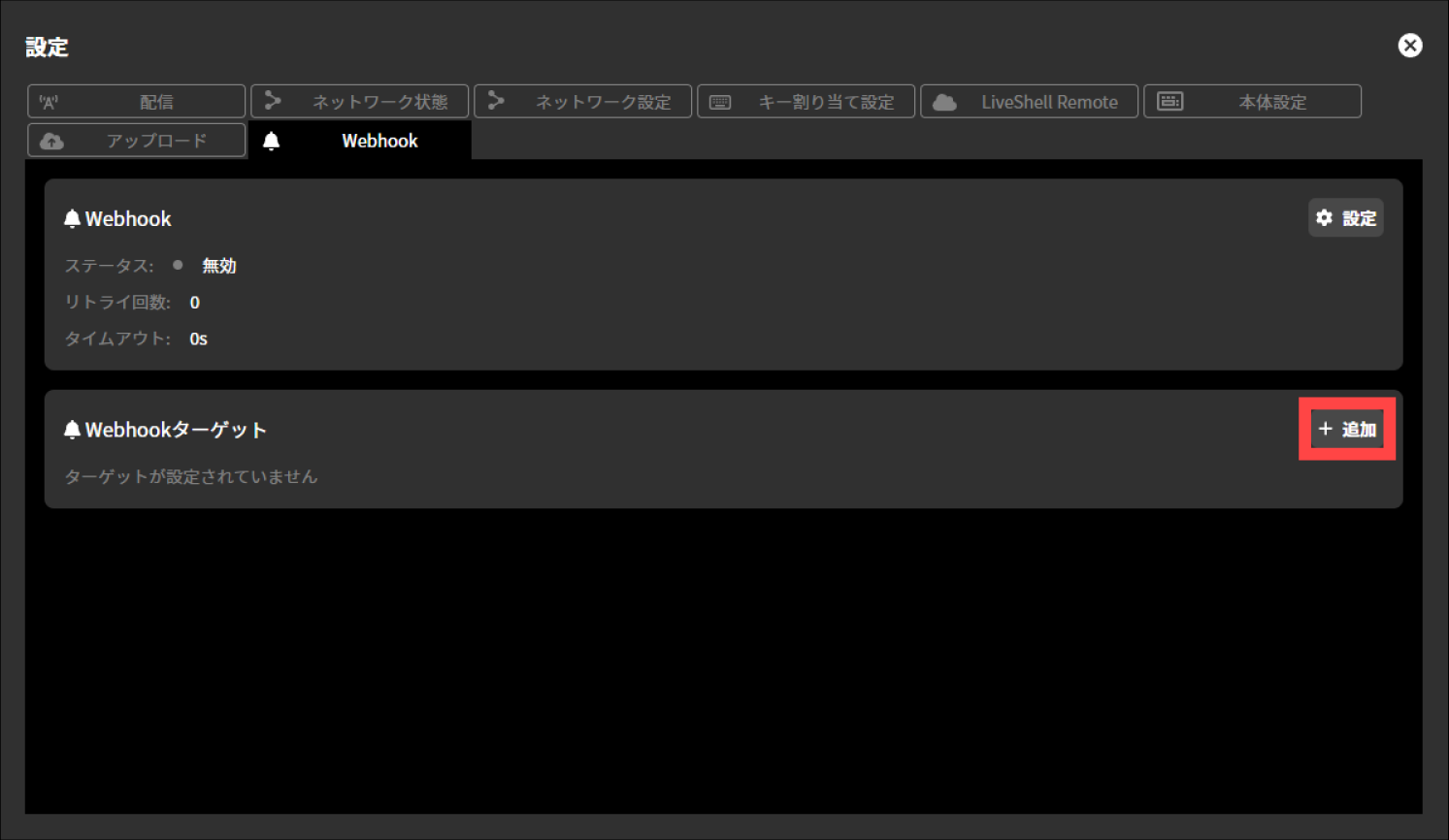
Make selections for each displayed setting and enter the desired values in the input fields. The available settings are as follows.
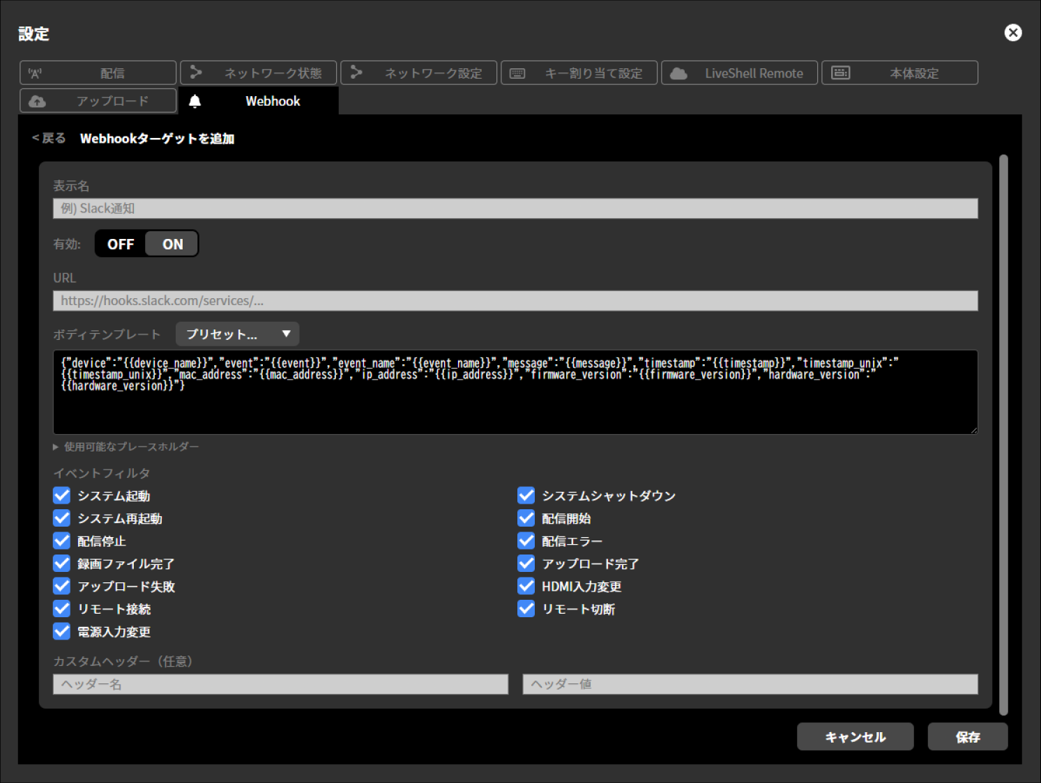
Display name
Enabled
OFF / ON
URL
Body Template
Preset
Slack-Simple
Slack-Rich
Discord-Simple
Discord-Rich
Teams-Simple
Teams-Rich
Generic JSON
Event Filter
System Startup
System Shutdown
System Restart
Streaming Start
Streaming Stop
Streaming Error
Recording File Completed
Upload Completed
Upload Failed
HDMI Input Change
Remote Connection
Remote Disconnection
Power Input Change
Custom Header (optional)
Header Name
Header Value
Press “Save”.
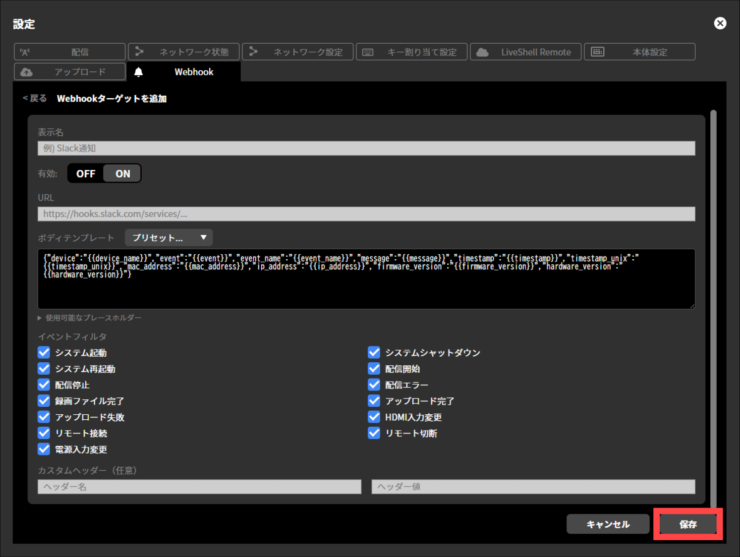
Management
Restoring to the Factory Default State
Unit menu / MAIN MENU →System →Factory Reset
LiveShell Studio / Settings →Device Settings tab →Reset to factory default
This describes how to delete all configuration information of this product and restore it to the factory default state. You can do this either from LiveShell Studio or by operating the unit.
Restoring to the Factory Default State by Operating the Unit
Use the control dial to navigate to MAIN MENU →System →, and select Factory Reset. Then press and hold video select button A for two seconds to perform the factory reset and restart.
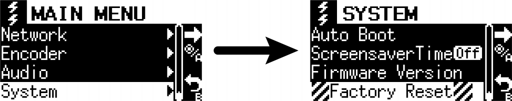
Restoring to the Factory Default State Using LiveShell Studio
Click “Reset to Factory Default” found in Settings →the Unit Settings tab. When you select “Yes” in the confirmation, the reset is performed and the unit restarts.

How to Force a Shutdown
If you need to force a shutdown, for example when this product can no longer be turned off by the normal shutdown operation (→How to shut down this product), either unplug the power supply cable or press and hold the power button on this product for at least 10 seconds.
How to Update the Firmware
How to Check Whether Updated Firmware Is Available
To check whether a firmware update is available for this product, perform the following operations in LiveShell Studio.
Click “Settings” at the top left of the LiveShell Studio application screen.
Click the “Unit Settings” tab on the settings screen that appears.
Click the “Check for Updates” button to the right of “Firmware Version”.
Check the message displayed to the right of the button.
If “This is the latest version.” is displayed, no firmware update is required.
If “An update is available. Click here to download.” is displayed, click that text and proceed to the next step.
Follow the instructions on the download page to perform the update.
How to Update the Firmware
The firmware update procedure is described in the separate document Firmware update guide.
When You Run Into Trouble
Frequently Asked Questions
Frequently asked questions are covered in the separate document Setup Guide.
Troubleshooting
Troubleshooting is covered in the separate document Setup Guide.
Error Messages
This chapter explains the error messages for this product.
Messages Displayed in LiveShell Studio
RTMP authentication error occurred in channel #1/2/3. Please set your account for RTMP server.
There is an error in the entries related to RTMP authentication. Please check your entries.
Streaming setting error occurred in channel #1/2/3. Please check the streaming setting.
There is an error in the entries related to streaming settings. Please check the streaming destination settings you entered, such as the RTMP URL and stream key.
A communication error occurred on channel #1/2/3. Stream closed by server.
The connection between this product and the destination server has been disconnected due to some reason. Please check the status of the connected network, etc.
SD card write error occurred in channel #1/2/3. Please set a writable SD card.
Writing to the SD card/USB drive is not working properly. Please check whether the SD card/USB drive is formatted in FAT32 or exFAT format.
No space on SD card/USB error occurred in channel #1/2/3. Please set SD card/USB that has free area.
There is not enough space on the SD card/USB Flash Drive. Delete files to free up space, or insert an SD card/USB Flash Drive with sufficient space.
No SD card/USB Flash Drive error occurred in channel #1/2/3. Please insert SD card/USB Flash Drive to record.
The SD card/USB drive is not recognized. Please insert/connect the SD card/USB drive to the main unit. If it is connected to the main unit, please check the connection status.
Unknown error occurred in channel #1/2/3.
Something is causing streaming or recording issues. Please check your settings and the status of your connected network.
Streaming operation error occurred in channel #1/2/3. Retry later.
Something is preventing the streaming operation from proceeding normally. Please try the streaming operation again. If the error persists, please check the settings and the status of the connected network.
Verified Live Streaming Services
The following is a list of streaming platforms with which we have verified streaming operation using LiveShell W (these are the results of our own independent verification and do not guarantee operation. Please also refrain from inquiring with the respective platform providers about these verification results).
Streaming Platform |
Recommended Encoder Settings for the Streaming Platform |
|---|---|
YouTube Live |
|
Niconico Live |
|
TwitCasting |
|
Facebook Live |
|
Twitch |
|
LINE Live |
|
Smart STREAM |
|
J-Stream Eqipmedia Live Edition |
|
17LIVE |
|
Mildom |
|
ClassStream |
|
ULIZA |
|
Wowza |
|
vimeo |
Specifications
Specification |
Unit |
Note |
|||
|---|---|---|---|---|---|
Encoding |
Video |
Video encoding |
H.264 |
||
Max resolution |
1920 × 1080 |
Dot |
|||
Max frame rate |
60 |
FPS |
|||
Output bitrate range |
128 ~ 20,480 |
kbit/s |
|||
Audio |
Audio encoding |
AAC-LC |
|||
Number of channels |
2 |
Channel |
|||
Sampling rate |
48 |
kHz |
|||
Bit depth |
16 |
bit |
|||
Output bitrate range |
48 ~ 256 |
kbit/s |
|||
Streaming |
Supported streaming protocols |
RTMP/RTMPS Client |
|||
Simultaneous streaming targets |
3 |
Target |
※ 各宛先は同一のエンコーダストリーム |
||
Recording |
Supported media |
microSD card or USB drive (formatted as exFAT or FAT32) |
|||
Recording stream |
The same encoder stream as the streaming output |
||||
Video manipulation |
Switching |
Number of inputs |
2 |
Input |
|
Switching effect |
Cut, Mix, Wipe |
||||
Video composite |
Composite effects |
Picture-in-Picture, Chroma Key |
|||
Caption composite |
Text placement, transparent PNG image composition |
※ 全画面の画像のみ対応 |
|||
Input interface |
Video |
Number of inputs |
2 |
Line |
|
Transmission method |
HDMI |
※ HDCPには対応していません |
|||
Supported input formats |
1080p/60(59.94), 1080p/50, 1080p/30(29.97), 1080p/25, 1080p/24(23.976), 1080i/60(59.94), 1080i/50, 720p/60(59.94), 720p/50, 720p/30(29.97), 720p/25, 720p/24(23.976), 576p/50, 480p/59.94, VGA |
※ HDMI 2系統利用時は両系統とも同一のフォーマットを入力する必要があります。 |
|||
I/P conversion |
Field coupling method |
※ インタレースフォーマットを入力した場合は、自動的にプログレッシブ変換します。 |
|||
Digital audio |
Number of inputs |
2 |
Line |
||
Transmission method |
HDMI Audio (shared with video input) |
||||
Analog audio |
Number of inputs |
2 |
Line |
||
Input connector |
LINE input, MIC input |
※ 各入力をHDMI Audioとミキシング可能 |
|||
Output interface |
Video |
Number of outputs |
1 |
Line |
※ プログラム確認映像出力用 |
Transmission method |
HDMI |
||||
Supported output formats |
1080p/60(59.94), 1080p/50, 1080p/30(29.97), 1080p/25, 1080p/24(23.976), 720p/60(59.94), 720p/50, 720p/30(29.97), 720p/25, 720p/24(23.976), 576p/50, 480p/59.94, VGA |
※ 入力フォーマットと同一のフォーマットで出力されます |
|||
Digital audio |
Number of outputs |
1 |
Line |
||
Transmission method |
HDMI Audio (shared with video output) |
||||
USB |
Number of ports |
2 |
Port |
※ 前面に1ポート、背面に1ポート |
|
Connectable devices (communication interface) |
Wireless LAN adapter or LTE connection modem |
||||
Connectable devices (others) |
Dedicated controller, HID keyboard, USB mass storage device, USB audio class device |
※ 専用コントローラは、企画中 |
|||
Network interface |
Wired connection |
Connection interface |
10BASE-T/100BASE-TX/1000BASE-T |
||
Number of ports (built into the main unit) |
1 |
Port |
|||
Wireless connection |
Connection interface |
Wireless LAN (802.11a/b/g/n/ac) or LTE |
※ 別途無線LANアダプタまたはLTE接続モデムが必要 |
||
Wireless LAN operation mode |
Infrastructure mode or AP mode |
||||
Network protocol |
IPv4 / IPv6 |
||||
Address setting method |
DHCP or fixed (IPv4), SLAAC (IPv6) |
||||
User interface |
Unit operation |
Display function |
128 × 64 dot OLED display |
||
Power operation |
Power button |
||||
Menu operation |
Control dial, button |
||||
Video/streaming operation |
Streaming button indicator, Video Select button A/B |
||||
External operation |
Built-in HTTP server |
Can be operated from a browser on a PC, tablet, etc. via the Ethernet LAN or wireless LAN interface |
|||
Built-in application |
LiveShell Studio |
||||
Power supply |
Input |
Number of inputs |
2 |
Port |
※ 電源冗長可能 |
Connector |
USB Type C |
||||
Voltage |
5 |
V |
|||
Max current |
3 |
A |
|||
Supported power supply |
AC adapter or portable power bank, etc. |
||||
Others |
Dimensions |
W 145 × D 100 × H 42 |
mm |
※ 突起部を除く |
|
Weight |
Approx. 500 |
g |
※ 本体のみ |
||
Accessories |
Accessories-sold-separately version (CDP-LS05A-SV) |
LiveShell W Quick Setup Guide |
|||
Accessories-included version (CDP-LS05A) |
LiveShell W Quick Setup Guide |
||||
Optional items sold separately |
Dedicated AC adapter (USB Type C-C cable included) |
||||
Wireless LAN adapter |
|||||
LTE connection modem |